 Contact Sales
  Spec Sheet
 Description
Features
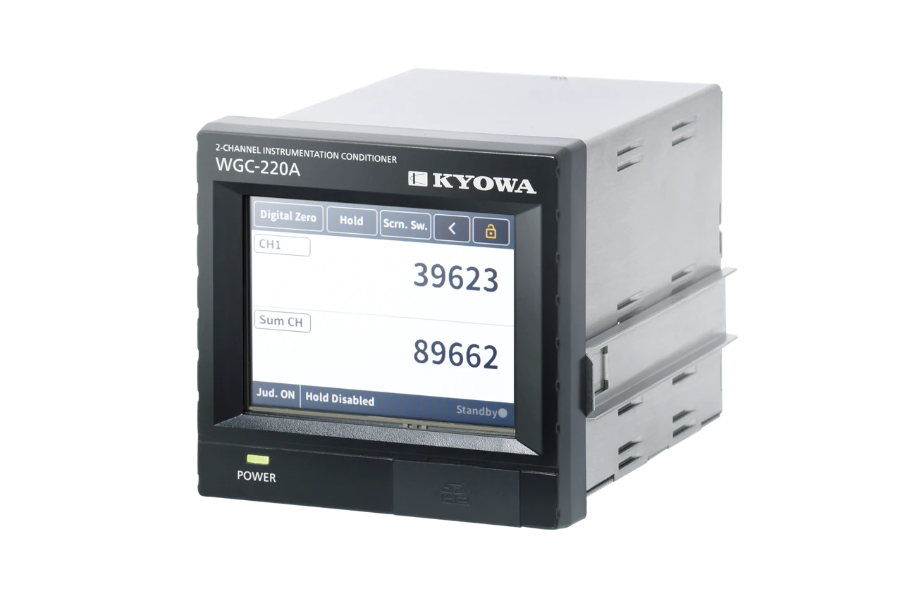
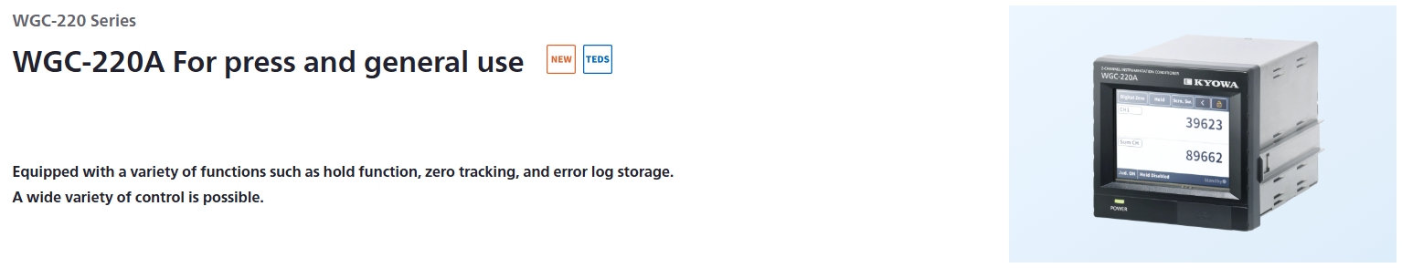
- Two-channel summation types with touch panel
- Operation functions included
- Variety of control I/O (input: 11, output: 15)
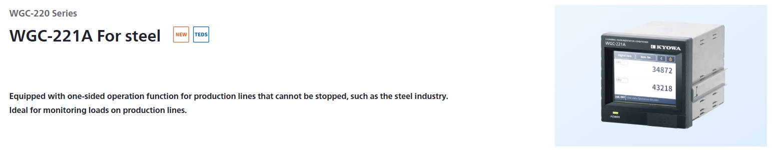
- With one-side operation function (WGC-221A)
Specifications
Strain Measuring part specifications*1
Item |
Details |
|
|---|---|---|
Number of Channels |
2 |
|
Input Connector |
Shape |
NDIS4109 (9 pins) receptacle Model: EPRC07-R9FNDIS |
Compatible Plug |
NDIS4109 (9 pins) plug Model: EPRC07-P9MNDIS |
|
Measuring Target |
Strain gage transducers |
|
Compatible Bridge Resistance |
When bridge excitation is 5 V: 87.5 to 1000 Ω
|
|
Bridge Excitation |
5, 10 VDC
|
|
Input Mode |
Balanced differential input |
|
Measuring Range |
Within ±3.2 mV/V |
|
Nonlinearity |
Within ±(0.02% FS +1 digit) |
|
Temperature Stability |
Zero Point |
Within ±0.25 μVRTI/ºC |
Sensitivity |
Within ±0.01 %/ºC |
|
Sampling Rate |
4000 times/sec. |
|
AD Resolution |
24 bits |
|
Connector For Analog Monitor |
Model |
ML-800-S1H-2P |
Analog Monitor |
Voltage Output |
±5 V (load resistance 5 kΩ or more) |
Output Accuracy |
Within ±200 mV |
|
TEDS |
Interface |
IEEE1451.4 Mixed Mode Transducer Interface Class2 |
Applicable Transducer: |
Should have information written in accordance with IEEEtemplate No. 33, cable length should be 30 m or less |
|
Low-pass Filter (Analog Monitor) |
Cutoff Frequency |
10, 30, 100, 300 Hz, None (1 kHz or over) |
Amplitude Ratio at Cutoff Frequency |
-3±1 dB |
|
Attenuation Characteristics |
-12±3 dB/oct. |
|
*1 Strain measuring part specifications apply to the state in which the temperature has stabilized after a preheating time of 30 minutes.
DA output specifications
Item |
Details |
|---|---|
Connector shape |
D-sub 15 pin |
Number of Output Channels |
8 |
Voltage Output |
±10 V (load resistance 2 kΩ or more) Scaling available |
Insulation Voltage |
250 VAC for 1 minute |
Conversion Speed |
4 kHz |
Nonlinearity |
Within ±0.1% FS |
Interface specifications
Item |
Details |
|
|---|---|---|
Indicators |
Type |
3.5 inch color LCD |
Display Area |
70.1 × 52.6 mm |
|
Resolution |
320 × 240 dots |
|
Touch Panel |
Resistive type |
|
Setting Range |
-99999 to +99999 count |
|
Update Speed |
Numeric value display: Approx.4 times/sec. |
|
RS-485*1 |
Connector Sshape |
D-sub 9 pin |
USB 2.0*1 |
Connector Shape |
Type-B |
Data Recording Media |
Type |
industrial-use SD card*2 |
Standard |
SDHC |
|
Capacity |
Up to 32 GB |
|
Format |
FAT 32 |
|
Control I/O Connector |
Model |
PCR-E36LMD-SL+ |
The Number of Points |
PCR-S36FS+
|
|
Control Input |
The Number of Points |
11 |
Type |
Zero command, TEDS command, diagnosis command, Level test command, lock command, Add value command, Error cancellation command, Pattern Selection command 1, Pattern Selection command 2, channel 1 × 2 command, channel 2 × 2 command |
|
Input Format |
Non-voltage contact signal, or Open collector (NPN) |
|
Output Voltage |
Approx. 12 VDC |
|
Output Current |
5 mA or less |
|
Control Output |
The Number of Points |
15 |
Type |
Comparator Output A, Comparator Output B, Comparator Output C, Comparator Output D, Comparator Output E, Comparator Output F, Comparator Output G, Comparator Output H, Judger
|
|
Output Format |
Open collector (NPN) |
|
Load Capacity |
30 VDC, 30 mA (resistance load) |
|
*1 Simultaneous RS-485 and USB communication is not possible.
*2 The following SD card has been tested by KYOWA.
Manufacturer: HAGIWARA Solutions
Model: NSDB-004GS(N24SEI
Capacity: 4 GB
Functional part specifications
Item |
Details |
|
|---|---|---|
Calibration |
Type |
Sensitivity Reg. Cal, Actual Load Cal, Numeric Value Reg. Cal, TEDS manual calibration, TEDS auto calibration
|
Sum CH |
1
|
|
Diff. CH |
1
|
|
Coefficient of Multiplication |
× 0.01 to × 10.00Target CH: Sum CH, Diff. CH (Individually configurable)
|
|
Decimal Point Position |
Arbitrary setting is available (common with All channels) |
|
Unit |
Can be set for each channel |
|
Filter |
Low-pass Filter |
10, 30, 100, 300 Hz, None (1 kHz or over) |
Moving Average |
None, 2, 5, 10, 20, 50, 100, 200, 500, 1000, 2000, 4000 times |
|
Minimum Scale |
1, 2, 5, 10, 20, 50, 100 |
|
Target CH |
Common with All channels |
|
Digital Zero |
Digital Zero Memory |
When executed by main unit operation: retainedBy Control input, by command: Hold/not hold selectable |
Noise Monitoring Width |
0 to 100% (Percentage value for 6.4 mV/V) |
|
Target CH |
CH1 & CH2 batch execution
|
|
Add Function |
Addition Value Enable |
Enable/Disable |
Addition Value |
0 to ±99999 countManual setting: Sets any value as an Addition Value and adds it.Tare Subtraction: Set the current measured value multiplied by -1 as the additive value and add. |
|
Target CH |
Manual setting:
|
|
Control of Add Function |
Manual, Control Input, Command |
|
One-side Operation |
Disable, CH1 × 2, CH2 × 2 |
|
Comparison |
The Number of Points |
8 |
Each Comparator Enable/Disable |
Selectable |
|
Target CH |
CH1, CH2, Sum CH, Diff. CH
|
|
Comparator Name |
Alphabet, Numerics, Symbol (max. 2 characters) |
|
Comparison Value |
±99999 count, Select over or under |
|
Display Color |
Select 1 color (total 8 colors) |
|
Comparator Output Logic |
Positive/ Negative |
|
Comparison Mode |
Always compare |
|
Hysteresis Width |
0 to 9999 count |
|
Comparison Speed |
4000 times/sec (When Always compare) |
|
Judgment |
The Number of Points |
1 |
Target Comparators |
Up to 4 of 8 Comparators can be selected |
|
Judgment Conditions |
AND, OR |
|
Judgment Output Logic |
Positive/ Negative |
|
Judgment Mode |
Always Judgment |
|
DA Output |
The Number of Points |
8 |
Each DA Output Enable/Disable |
Selectable |
|
Target CH |
CH1, CH2, Sum CH, Diff. CH |
|
DA Output Assignment |
Measured value |
|
Scaling |
Zero Display Value
|
|
Auto Scaling |
Enable/Disable
|
|
Reflects Minimum Scale |
Enable/Disable |
|
Display Settings |
Number of Channels Displayed |
1, 2, 4 |
Indication |
Numerics |
|
Comparator Name |
Alphabet, Numerics, Symbol (max. 8 characters) |
|
Display Value Averaging |
Enable/Disable |
|
Setting Pattern |
The Number of Patterns |
4 |
Setting Range |
Each Calibration value, Addition value, Comparison function settings, Judgment function settings, Digital Zero Values, DA Output function settings |
|
Control of Setting Pattern |
Manual, Control Input, Command |
|
Communication Settings |
Interface |
USB, RS-485 |
Transmission Speed Setting |
9600, 19200, 38400 bps |
|
Delimiter Setting |
Received Delimiter: CR, LF, CRLF
|
|
Device ID |
01 to 99 (RS-485 only) |
|
Transmission Mode |
Tx and Rx |
|
Check function |
Original Value Check |
Display range: -3.2000 to 3.2000 mV/V (5 digits)
|
Level Test |
Arbitrary values can be displayedLevel Test Value:
|
|
Power-on Check |
Enable/Disable
|
|
Other Checks |
Bridge Excitation, Control I/O, Communication, SD card, Built-in Memory, Touch Panel, Display Color, LED |
|
Data |
Setting Save |
Save all settings to SD card |
Setting Read |
Read all settings from SD card |
|
Configuration Settings |
Language (Japanese/English), Backlight off Time, Date & Time,Version, Update, SD Card Format, Set Initialize |
|
General specifications
Item |
Details |
|---|---|
Power Connector |
M3 terminal block |
Power Supply |
100 to 240 VAC 50 / 60 Hz |
Power Consumption |
20 VA or less (at 100 VAC) |
Operating Temperature Humidity |
-10 to 40 ºC, 20 to 85% (Noncondensing) |
Storage Temperature |
-20 to 50 ºC |
Dimensions |
100 (W) × 96 (H) × 135 (D) mm (Not include protrusions) |
Weight |
Approx. 970 g |
Port |
GND port M4 Bind |
* Concentrations of the 10 restricted substances designated in ANNEXII of RoHS Directive are less than the maximum allowable (excluding exceptions for applying usage prohibition measures).
Optional Accessories |
100 VAC power cable (1.0 m) P-23
|
|---|
Dimensions

Specifications
Strain Measuring part specifications*1
Item |
Details |
|
|---|---|---|
Number of Channels |
2 |
|
Input Connector |
Shape |
NDIS4109 (9 pins) receptacle Model: EPRC07-R9FNDIS |
Compatible Plug |
NDIS4109 (9 pins) plug Model: EPRC07-P9MNDIS |
|
Measuring Target |
Strain gage transducers |
|
Compatible Bridge Resistance |
When bridge excitation is 5 V: 87.5 to 1000 Ω
|
|
Bridge Excitation |
5, 10 VDC
|
|
Input Mode |
Balanced differential input |
|
Measuring Range |
Within ±3.2 mV/V |
|
Nonlinearity |
Within ±(0.02% FS +1 digit) |
|
Temperature Stability |
Zero Point |
Within ±0.25 μVRTI/ºC |
Sensitivity |
Within ±0.01 %/ºC |
|
Sampling Rate |
4000 times/sec. |
|
AD Resolution |
24 bits |
|
Connector For Analog Monitor |
Model |
ML-800-S1H-2P |
Analog Monitor |
Voltage Output |
±5 V (load resistance 5 kΩ or more) |
Output Accuracy |
Within ±200 mV |
|
TEDS |
Interface |
IEEE1451.4 Mixed Mode Transducer Interface Class2 |
Applicable Transducer: |
Should have information written in accordance with IEEEtemplate No. 33, cable length should be 30 m or less |
|
Low-pass Filter (Analog Monitor) |
Cutoff Frequency |
10, 30, 100, 300 Hz, None (1 kHz or over) |
Amplitude Ratio at Cutoff Frequency |
-3±1 dB |
|
Attenuation Characteristics |
-12±3 dB/oct. |
|
*1 Strain measuring part specifications apply to the state in which the temperature has stabilized after a preheating time of 30 minutes.
DA output specifications
Item |
Details |
|---|---|
Connector shape |
D-sub 15 pin |
Number of Output Channels |
8 |
Voltage Output |
±10 V (load resistance 2 kΩ or more) Scaling available |
Insulation Voltage |
250 VAC for 1 minute |
Conversion Speed |
4 kHz |
Nonlinearity |
Within ±0.1% FS |
Interface specifications
Item |
Details |
|
|---|---|---|
Indicators |
Type |
3.5 inch color LCD |
Display Area |
70.1 × 52.6 mm |
|
Resolution |
320 × 240 dots |
|
Touch Panel |
Resistive type |
|
Setting Range |
-99999 to +99999 count |
|
Update Speed |
Numeric value display: Approx.4 times/sec. |
|
RS-485*1 |
Connector Sshape |
D-sub 9 pin |
USB 2.0*1 |
Connector Shape |
Type-B |
Data Recording Media |
Type |
industrial-use SD card*2 |
Standard |
SDHC |
|
Capacity |
Up to 32 GB |
|
Format |
FAT 32 |
|
Control I/O Connector |
Model |
PCR-E36LMD-SL+ |
The Number of Points |
PCR-S36FS+
|
|
Control Input |
The Number of Points |
11 |
Type |
Zero command, TEDS command, diagnosis command, Level test command, lock command, Add value command, Error cancellation command, Pattern Selection command 1, Pattern Selection command 2, Hold command, Reset command |
|
Input Format |
Non-voltage contact signal, or Open collector (NPN) |
|
Output Voltage |
Approx. 12 VDC |
|
Output Current |
5 mA or less |
|
Control Output |
The Number of Points |
15 |
Type |
Comparator Output A, Comparator Output B, Comparator Output C, Comparator Output D, Comparator Output E, Comparator Output F, Comparator Output G, Comparator Output H, Judger
|
|
Output Format |
Open collector (NPN) |
|
Load Capacity |
30 VDC, 30 mA (resistance load) |
|
*1 Simultaneous RS-485 and USB communication is not possible.
*2 The following SD card has been tested by KYOWA.
Manufacturer: HAGIWARA Solutions
Model: NSDB-004GS(N24SEI
Capacity: 4 GB
Functional part specifications
Item |
Details |
|
|---|---|---|
Calibration |
Type |
Sensitivity Reg. Cal, Actual Load Cal, Numeric Value Reg. Cal, TEDS manual calibration, TEDS auto calibration
|
Sum CH |
1
|
|
Diff. CH |
1
|
|
Coefficient of Multiplication |
× 0.01 to × 10.00Target CH: Sum CH, Diff. CH (Individually configurable)
|
|
Decimal Point Position |
Arbitrary setting is available (common with All channels) |
|
Unit |
Can be set for each channel |
|
Filter |
Low-pass Filter |
10, 30, 100, 300 Hz, None (1 kHz or over) |
Moving Average |
None, 2, 5, 10, 20, 50, 100, 200, 500, 1000, 2000, 4000 times |
|
Minimum Scale |
1, 2, 5, 10, 20, 50, 100 |
|
Target CH |
Common with All channels |
|
Digital Zero |
Digital Zero Memory |
When executed by main unit operation: retainedBy Control input, by command: Hold/not hold selectable |
Noise Monitoring Width |
0 to 100% (Percentage value for 6.4 mV/V) |
|
Target CH |
CH1 & CH2 batch execution
|
|
Zero Tracking |
Zero Tracking Enable |
Enable/Disable
|
Judging Time |
0.01 to 9.99 sec |
|
Compensation Range |
0 to 99999 count |
|
Target CH |
CH1 & CH2 batch execution |
|
Add Function |
Addition Value Enable |
Enable/Disable |
Addition Value |
0 to ±99999 countManual setting: Sets any value as an Addition Value and adds it.Tare Subtraction: Set the current measured value multiplied by -1 as the additive value and add. |
|
Target CH |
Manual setting:
|
|
Control of Add Function |
Manual, Control Input, Command |
|
Hold |
Hold Enable |
Enable/Disable |
Operation Mode |
Block Detect, Block Hold, Time Hold, Arbitrary Hold |
|
Detection Type |
Peak, Bottom, Peak to Peak, Average
|
|
Detection Time |
0.01 to 9.99 sec |
|
Delay Time |
0.00 to 9.99 sec |
|
Hold Value During the Detecting Block |
Measured value constantly updated,measured value at holding enable |
|
Target CH |
Batch execution of all channels. |
|
Comparison |
The Number of Points |
8 |
Each Comparator Enable/Disable |
Selectable |
|
Target CH |
CH1, CH2, Sum CH, Diff. CH
|
|
Comparator Name |
Alphabet, Numerics, Symbol (max. 2 characters) |
|
Comparison Value |
±99999 count, Select over or under |
|
Display Color |
Select 1 color (total 8 colors) |
|
Comparator Output Logic |
Positive/ Negative |
|
Comparison Mode |
Always compare, Compare at hold moment |
|
Hysteresis Width |
0 to 9999 count |
|
Comparison Speed |
4000 times/sec (When Always compare) |
|
Judgment |
The Number of Points |
1 |
Target Comparators |
Up to 4 of 8 Comparators can be selected |
|
Judgment Conditions |
AND, OR |
|
Judgment Output Logic |
Positive/ Negative |
|
Judgment Mode |
Always Judgment, Judge at hold moment |
|
DA Output |
The Number of Points |
8 |
Each DA Output Enable/Disable |
Selectable |
|
Target CH |
CH1, CH2, Sum CH, Diff. CH |
|
DA Output Assignment |
Measured value, Hold Value |
|
Scaling |
Zero Display Value
|
|
Auto Scaling |
Enable/Disable
|
|
Reflects Minimum Scale |
Enable/Disable |
|
Display Settings |
Number of Channels Displayed |
1, 2, 4 |
Indication |
Numerics |
|
Comparator Name |
Alphabet, Numerics, Symbol (max. 8 characters) |
|
Zero nearly Zero |
Enable/DisableSetting range: 1 to 9 count
|
|
Display Value Averaging |
Enable/Disable |
|
Setting Pattern |
The Number of Patterns |
4 |
Setting Range |
Comparison function settings, Judgment function settings, Hold function settings |
|
Control of Setting Pattern |
Manual, Control Input, Command |
|
Communication Settings |
Interface |
USB, RS-485 |
Transmission Speed Setting |
9600, 19200, 38400 bps |
|
Delimiter Setting |
Received Delimiter: CR, LF, CRLF
|
|
Device ID |
01 to 99 (RS-485 only) |
|
Transmission Mode |
Output at Hold (USB only), Tx and Rx (USB, RS-485) |
|
Error Log Settings
|
Recorded Data |
Hold Values recorded from the time the target Comparator is turnedON up to 30 second before are recorded on the SD card |
Error Log |
Enable/Disable |
|
Target Comparator |
Select from 8 comparators, multiple comparators can be selected |
|
Recording Time |
30 sec. |
|
Check function |
Original Value Check |
Display range: -3.2000 to 3.2000 mV/V (5 digits)
|
Level Test |
Arbitrary values can be displayedLevel Test Value:
|
|
Power-on Check |
Enable/Disable
|
|
Other Checks |
Bridge Excitation, Control I/O, Communication, SD card, Built-in Memory, Touch Panel, Display Color, LED |
|
Data |
Setting Save |
Save all settings to SD card |
Setting Read |
Read all settings from SD card |
|
Checking Error Log
|
Displays up to the latest 20 files and allows confirmation of file names (Data references are not allowed).Deletion of the displayed file is possible. |
|
Configuration Settings |
Language (Japanese/English), Backlight off Time, Date & Time,Version, Update, SD Card Format, Set Initialize |
|
General specifications
Item |
Details |
|---|---|
Power Connector |
M3 terminal block |
Power Supply |
100 to 240 VAC 50 / 60 Hz |
Power Consumption |
20 VA or less (at 100 VAC) |
Operating Temperature Humidity |
-10 to 40 ºC, 20 to 85% (Noncondensing) |
Storage Temperature |
-20 to 50 ºC |
Dimensions |
100 (W) × 96 (H) × 135 (D) mm (Not include protrusions) |
Weight |
Approx. 970 g |
Port |
GND port M4 Bind |
* Concentrations of the 10 restricted substances designated in ANNEXII of RoHS Directive are less than the maximum allowable (excluding exceptions for applying usage prohibition measures).
Optional Accessories |
100 VAC power cable (1.0 m) P-23
|
|---|
Dimensions
