 Contact Sales
  Spec Sheet
 Description
Features
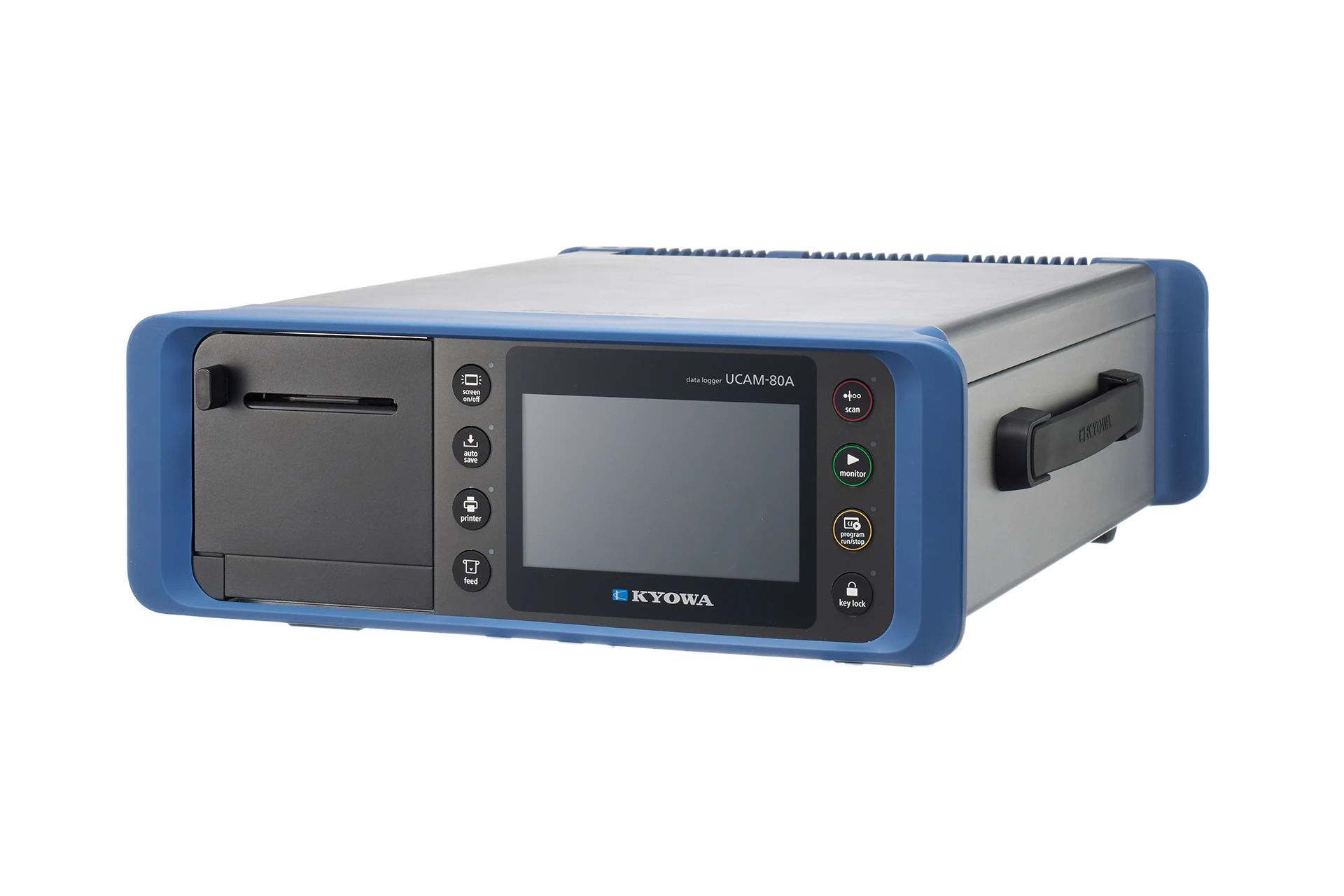
- Our long-selling static strain measuring instrument now features even better design and usability.
- Received the 2024 Good Design Award
- Precise measurements up to high-elongation strain (High-resolution 0.1 × 10⁻⁶ strain, capable of measuring up to 20000 × 10-6 strain (in the case of a full-bridge system))
- Intuitive touch panel operation
Contents
【Data Logger】
UCAM-80A
【Dedicated Scanners】
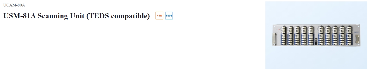
USM-81A (TEDS compatible)
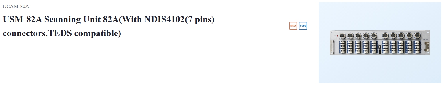
USM-82A (With NDIS4102 (7 pins) connectors, TEDS compatible)
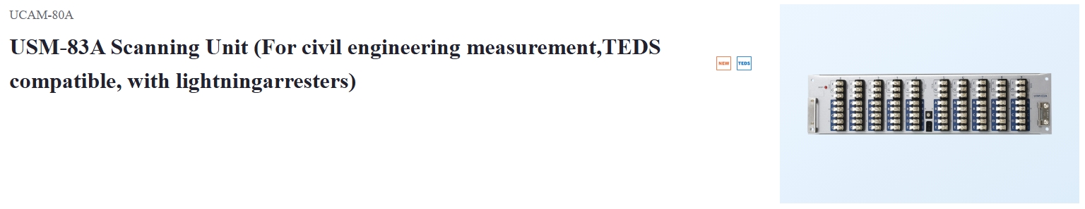
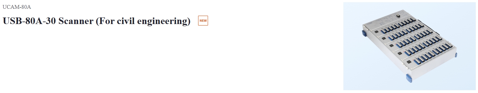
USM-83A (For civil engineering, with lightning arresters, TEDS compatible)
【External Scanners】
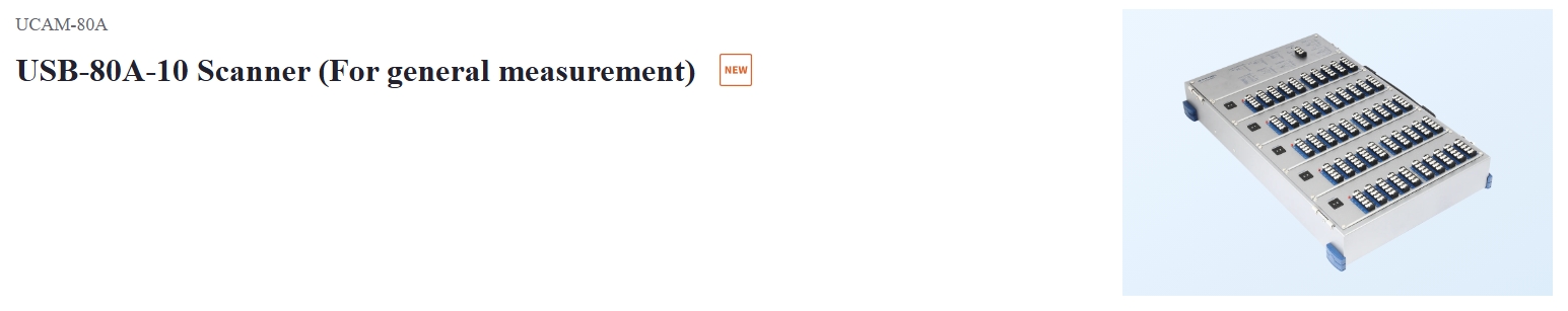
USB-80A
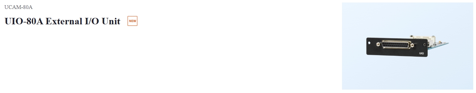
【External I/O Unit】
UIO-80AContents
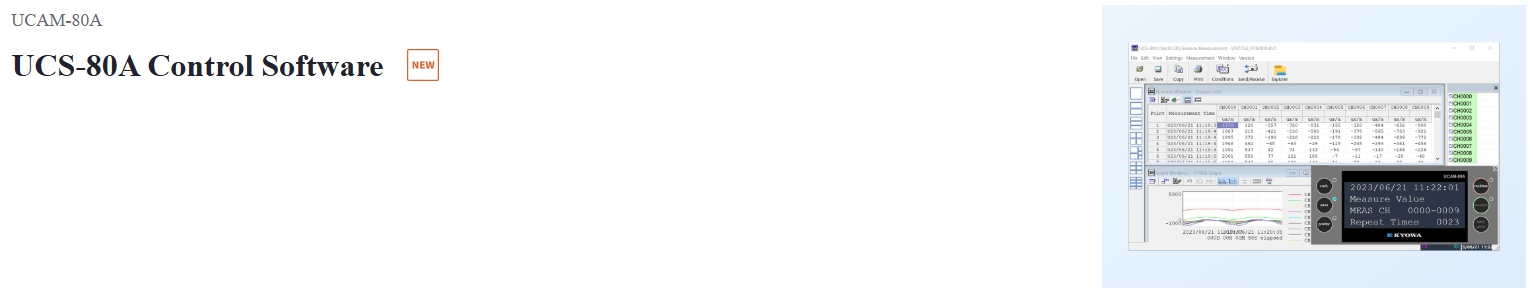
【Control Software】
UCS-80A
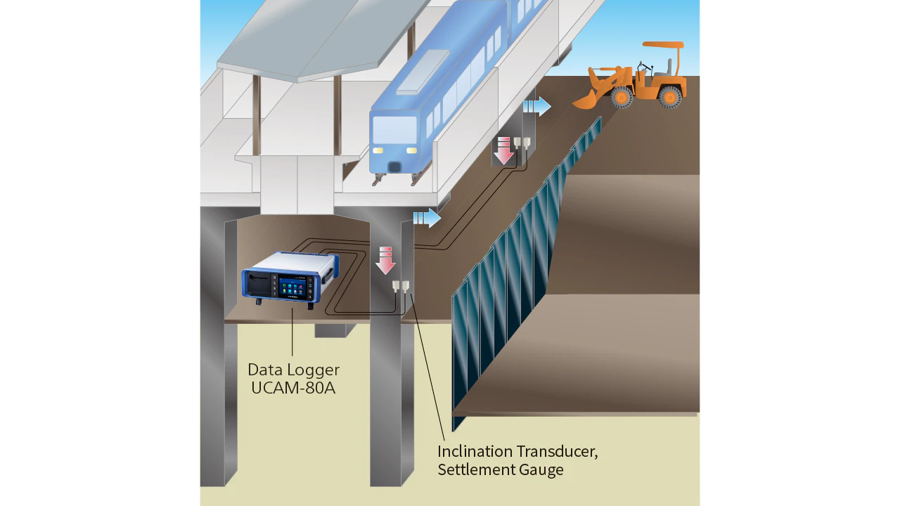
Measurement of Changes due to Nearby Construction
UCAM-80A can be used to measure changes to management values throughout construction when building near existing structures, to manage safety throughout the construction period. It features more built-in memory than the conventional models (UCAM-60A/B), allowing for multipoint measurements to be taken over a longer period.
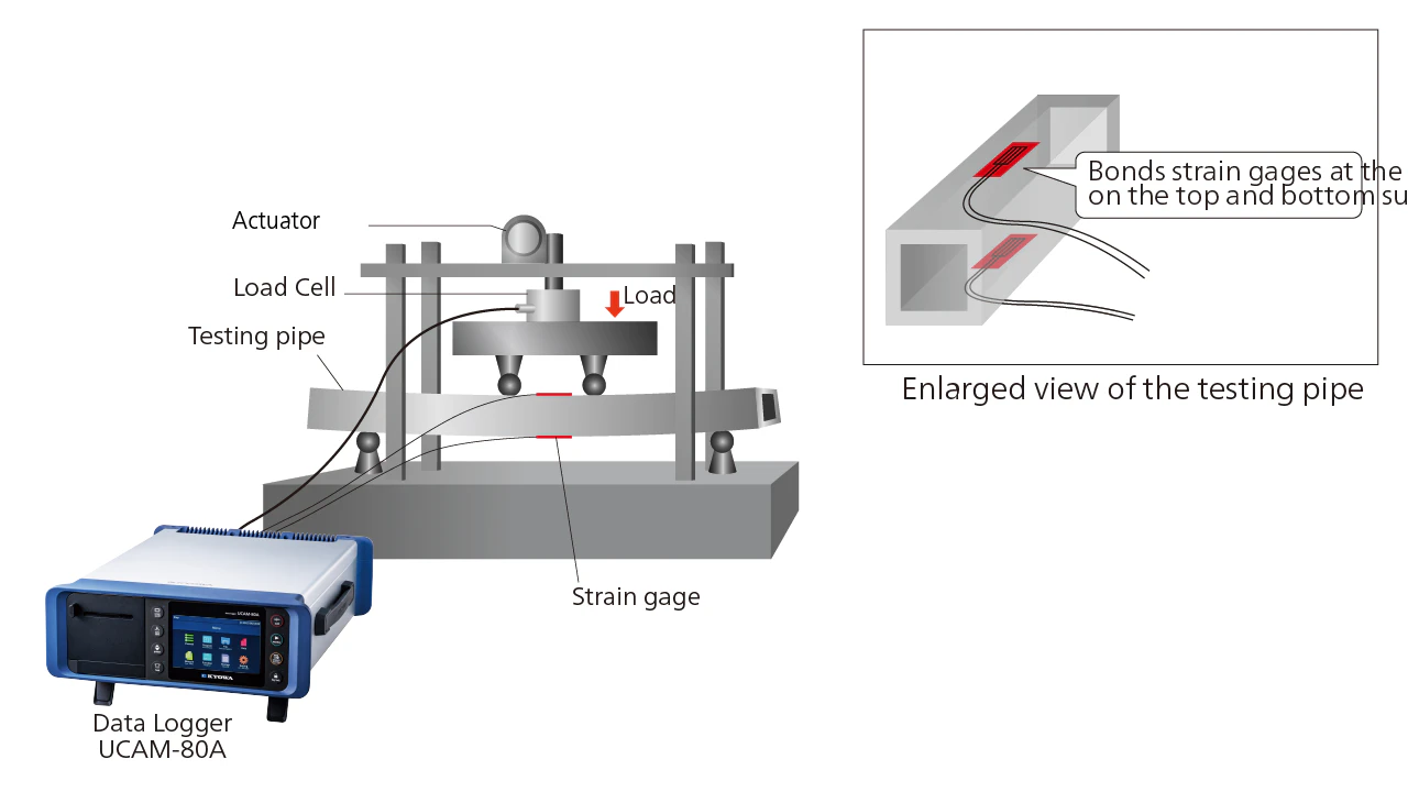
Hollow Aluminum Rectangular Pipe Strength Measurement
UCAM-80A provides highly-accurate high-elongation strain measurement, and can be used to measure strain from the elastic region to the plastic region. The built-in printer can also be used to print measurement results at the site.
Specifications
Measuring Targets and Connectable Scanners
Measuring Targets |
Strain gages, strain gage transducers, civil engineering transducers with a thermal sensor, DC voltage-output or DC current-output instruments, potentiometer sensors, thermal sensors(Thermocouples and platinum resistance thermometer bulbs) |
|---|---|
Connectable Scanning Units(mounted on top of the UCAM-80A) |
USM-81A, USM-82A, USM-83A(Accessory terminal cover can be attached) |
Connectable Scanners |
USB-80/70 series |
Measuring Targets and Connectable Scanners |
Measuring Targets: Strain gages and Straingage transducers (*1)・Quarter bridge system: 120 Ω, 240 Ω, 350 ΩScanners:[Scanning Units]USM-81A, USM-82A, USM-83A, USS-61B (*3), USS-62B (*3), USS-63B (*3)[External Scanners]General purpose: USB-80A-10, USB-80A-20, USB-70A/B-10, USB-70A/B-20Civil engineering: USB-80A-30, USB-70A/B-30・Quarter bridge (true-dummy system): 120 Ω, 350 ΩScanners:[Scanning Units]USM-81A, USM-82A, USM-83A, USS-61B (*3), USS-62B (*3), USS-63B (*3)[External Scanners]General purpose: USB-80A-10, USB-80A-20, USB-70A/B-10, USB-70A/B-20Civil engineering: USB-80A-30, USB-70A/B-30・Half bridge 60 to 1000 Ω: Active dummy system, Active Active systemScanners:[Scanning Units]USM-81A, USM-82A, USM-83A, USS-61B (*3), USS-62B (*3), USS-63B (*3)[External Scanners]General purpose: USB-80A-10, USB-80A-20, USB-70A/B-10, USB-70A/B-200Civil engineering: USB-80A-30, USB-70A/B-30・Half bridge 60 to 1000 Ω: Common Dummy systemScanners:[External Scanners]General purpose: USB-80A-10, USB-80A-20, USB-70A/B-10, USB-70A/B-20Civil engineering: USB-80A-30, USB-70A/B-30・Full bridge 60 to 1000 Ω(*2): Opposite-leg active system, Full bridge systemScanners:[Scanning Units]USM-81A, USM-82A, USM-83A, USS-61B (*3), USS-62B (*3), USS-63B (*3)[External Scanners]General purpose: USB-80A-10, USB-80A-20, USB-70A/B-10, USB-70A/B-20Civil engineering: USB-80A-30, USB-70A/B-30Measuring Targets: Civil engineering transducers・Full bridge 120 Ω: Constant-current excitation[Scanning Units]USM-81A, USM-82A, USM-83A, USS-61B (*3), USS-62B (*3), USS-63B (*3)・Full bridge 350 Ω: Constant-current excitationScanners:[Scanning Units]USM-81A, USM-82A, USM-83A, USS-61B (*3), USS-62B (*3), USS-63B (*3)[External Scanners]General purpose: USB-80A-10, USB-80A-20, USB-70A/B-10, USB-70A/B-20Civil engineering: USB-80A-30, USB-70A/B-30・Full bridge 350 Ω: Transducers with a thermal sensorScanners:[Scanning Units]USM-81A, USM-82A, USM-83Am, USS-61B (*3), USS-62B (*3), USS-63B (*3)[External Scanners]Civil engineering: USB-80A-30, USB-70A/B-30Measuring Targets: Voltage・DC voltage-output instrumentsScanners:[Scanning Units]USM-81A, USM-82A, USM-83A, USS-61B (*3), USS-62B (*3), USS-63B (*3)[External Scanners]General purpose: USB-80A-10, USB-80A-20, USB-70A/B-10, USB-70A/B-20Civil engineering: USB-80A-30, USB-70A/B-30Measuring Targets: Current・DC current-output instrumentsScanners:[Scanning Units]USM-81A, USM-82A, USM-83A, USS-61B (*3), USS-62B (*3), USS-63B (*3)[External Scanners]General purpose: USB-80A-10, USB-80A-20, USB-70A/B-10, USB-70A/B-20Civil engineering: USB-70B-30Measuring Targets: Temperature・Thermocouples: K(CA), T(CC), E(CRC), J(IC), RScanners:[Scanning Units]USM-81A, USM-82A, USM-83A, USS-61B (*3), USS-62B (*3), USS-63B (*3)[External Scanners]General purpose: USB-80A-10, USB-80A-20, USB-70A/B-10, USB-70A/B-20Civil engineering: USB-80A-30, USB-70A/B-30・Platinum Resistance Thermometer bulbs: Pt100(new JIS), JPt100(old JIS)Scanners:[Scanning Units]USM-81A, USM-82A, USM-83A, USS-61B (*3), USS-62B (*3), USS-63B (*3)[External Scanners]Civil engineering: USB-80A-30, USB-70A/B-30Measuring Targets: Potentiometer sensorsScanners:[Scanning Units]USM-81A, USM-82A, USM-83A, USS-61B (*3), USS-62B (*3), USS-63B (*3)[External Scanners]General purpose: USB-80A-10, USB-80A-20, USB-70A/B-10, USB-70A/B-20Civil engineering:USB-80A-30, USB-70A/B-30Measuring Targets: Built-in lighting arrestersScanners:[Scanning Units]USM-83A, USS-63B only[External Scanners]Civil engineering: USB-80A-30, USB-70A/B-30*1. Can not use remote sensing sensor directly.*2. 120 to 1000 Ω in high-resolution mode.*3. Accessory terminal cover not attachable. When mounted on the UCAM-80A, calibration is required.(with charge) |
Input Channels |
Max 30 with Scanning UnitsMax 1000 with External Scanners connectedMax 1000 with Scanning Units and External Scanners connected |
|---|---|
Scanning Speed |
Scanning Units (standard mode)Line Frequencies(50 Hz/ 60 Hz Zone): 50 ms/ channelScanning Units (High-resolution mode)Line Frequencies(50 Hz/ 60 Hz Zone): 280 ms/ channelScanning Units (High-speed mode)Line Frequencies(50 Hz Zone): 20 ms/channelLine Frequencies(60 Hz Zone): 16.7 ms/channelUSB-80/70 series(standard mode only)Line Frequencies(50 Hz Zone): 60 ms/channelLine Frequencies(60 Hz Zone): 58.4 ms/channelNotes:1.Scanning speeds stated above are standard maximum speeds in respective modes. Besides these,the following speeds are set for each individual channel:0.28 s, 0.5 s, 1s ,2 s, 5 s, and 10 s.2. Repeat measurement interval time = (Number of Measuring channels * scanning speed ) + data processing time (Less than 5 seconds)Data processing time is indeterminate,changed by measurement setting and environment.Data processing time is when the printer is set to not print.3. Standard mode and High-resolution mode can be set for each channel.4. High-speed mode is only collective switching for all channels of Scanning Units.[Measuring Targets & Scanning Mode]Measuring Targets: Strain(Gage & transducer)Scanning speed: Standard Mode, High-resolution Mode, High-speed ModeMeasuring Targets: Voltage/current-output sensorScanning speed: Standard Mode, High-speed ModeMeasuring Targets: Civil engineering transducerScanning speed: Standard ModeMeasuring Targets: Temperature sensor(TC, Pt)Scanning speed: Standard ModeMeasuring Targets: Potentiometer sensorScanning speed: Standard Mode, High-speed ModeNotes:1. High-resolution mode and high-speed mode can be measured only with the Scanning Units , not with the USB-80/70 series.2. In high-resolution mode and high-speed mode, strain mode is Full bridge system only. |
Operating Modes |
Real-time, monitor, and automatic |
Measurement Functions |
・Initial Initial values are measured and stored in internal memory.・Original Raw values are measured without subtraction of initial values.・Measure Initial values are subtracted from original values.Notes: The selected function is applied to all channels. |
Coefficient Calculation Function |
Multiplication by calibration coefficient, calibration by TEDS, conversion of measured values to physical quantities, scaling and correction |
Unit |
59 units |
Automatic Measurement Function
Trigger Measurement |
A relative value (certain changing quantity) or an absolute value triggers measurement. |
|---|---|
Interval Measurement |
Measurement is automatically performed at preset time intervals. |
Trigger Interval Measurement |
Combination of trigger measurement and interval measurement. |
Change stroke measurement |
Single channel only |
|---|---|
Storage |
Internal memory, approx. 1.8 GB |
Strain Measurement (Standard Mode)
Constant Voltage Excitation |
Approx. 2 or 5 VDC |
|---|---|
Constant Current Excitation |
Approx. 5.7 mA(Bridge resistance 350 Ω)
|
Scanning Speed |
50 ms/channel |
Gage Factor |
2.00 fixed (Coefficient calculation function enables correction with 2.00/Ks) |
Initial Value Memory Range |
Same as measuring range |
Measuring Range, Resolution and Accuracy |
Measuring Range: 0 to ±50k ×10-6 strain
|
Strain Measurement (High-resolution Mode)
Constant Voltage Excitation |
Approx. 5 VDC |
|---|---|
Constant Current Excitation |
Approx. 14.3 mA(Bridge resistance 350 Ω) |
Scanning Speed |
0.28 s/channel |
Gage Factor |
2.00 fixed (Coefficient calculation function enables correction with 2.00/Ks) |
Initial Value Memory Range |
Same as measuring range |
Measuring Range, Resolution and Accuracy |
Measuring Range: 0 to ±20k ×10-6 strain
|
Strain Measurement (High-speed Mode)
Constant Voltage Excitation |
Approx. 2 VDC |
|---|---|
Constant Current Excitation |
Approx. 5.7 mA(Bridge resistance 350 Ω)Approx. 16.7 mA(Bridge resistance 120 Ω) |
Scanning Speed |
20 ms/channel(50 Hz Zone),16.7 ms/channel(60 Hz Zone) |
Gage Factor |
2.00 fixed (Coefficient calculation function enables correction with 2.00/Ks) |
Initial Value Memory Range |
Same as measuring range |
Measuring Range, Resolution and Accuracy |
Measuring Range: 0 to ±50k ×10-6 strainResolution: 1×10⁻⁶ strainAccuracy: ±(0.08% of reading+3) ×10-6 strainMeasuring Range: ±50k to ±500k ×10-6 strainResolution: 10×10-6 strainAccuracy: ±(0.05% of reading+30) ×10-6 strainNotes:1.Available only with full bridges system(120 to 1000 Ω)2.Available only with Scanning Units.3.Resolution and accuracy be automatically change by Autorange function. |
Voltage Measurement (Standard Mode)
Scanning Speed |
50 ms/channel |
|---|---|
Initial Value Memory Range |
Same as measuring range |
Voltage Measurement (High-speed Mode)
Measuring range,Resolution and Accuracy |
・Range Mode: V/500 mV
|
|---|---|
Scanning Speed |
20 ms/channel(50 Hz Zone), 16.7 ms/channel(60 Hz one) |
Initial Value Memory Range |
Same as measuring range |
Measuring Range, Resolution and Accuracy |
・Range Mode: V/500 mV
|
Current Measurement (Standard Mode)
Scanning Speed |
50 ms/channel |
|---|---|
Initial Value Memory Range |
Same as measuring range |
Measuring Range, Resolution and Accuracy |
Channel Mode: I/50 mA
|
Current Measurement (High-speed Mode)
Scanning Speed |
20 ms/channel(50 Hz Zone), 16.7 ms/channel(60 Hz one) |
|---|---|
Initial Value Memory Range |
Same as measuring range |
Measuring Range, Resolution and Accuracy |
Channel Mode: I/50 mA
|
Temperature Measurement with Thermocouple (Standard Mode)
Scanning Speed |
50 ms/channel |
|---|---|
Measuring Range, Resolution and Accuracy |
[K-TYPE]
|
Temperature Measurement with Civil Engineering Transducers with a Thermal Sensor (Standard Mode)
Scanning Speed |
50 ms/channel |
|---|---|
Measuring Range, Resolution and Accuracy |
Measuring range: -50.0 to 200.0°C
|
Temperature Measurement with Platinum Resistance Thermometer Bulb (Standard Mode)
Scanning Speed |
50 ms/channel |
|---|---|
Measuring Range, Resolution and Accuracy |
Type: Pt100
|
Measurement with Potentiometer Sensor (Standard Mode)
Scanning Speed |
50 ms/channel |
|---|---|
Initial Value Memory Range |
Same as measuring range |
Sensor Power Supply |
Approx. 2 VDC |
Potentiometer Resistance |
1 kΩ to 10 kΩ |
Measuring Range, Resolution and Accuracy |
Channel Mode: POT.
|
Measurement with Potentiometer Sensor (High-speed Mode)
Scanning Speed |
20 ms/channel (50 Hz Zone), 16.7 ms/channel (60 Hz one) |
|---|---|
Initial Value Memory Range |
Same as measuring range |
Sensor Power Supply |
Approx. 2 VDC |
Potentiometer Resistance |
1 kΩ to 10 kΩ |
Measuring Range, Resolution and Accuracy |
Channel Mode: POT.
|
Temperature Stability |
[Zero poin]t:
|
|---|---|
Internal Timer |
Real time clock is Built-in (Battery backup)
|
Display |
5-inch color display (TFT)
|
Speaker |
Sounds when operated or when an error occurs |
Printer |
Printing Thermal
|
Interface |
・To PC interface:
|
File Conversion |
Measurement data can be converted to CSV. |
Self–diagnosis Functions |
Checks display, printer, bridge excitation, lead-wire-off, input/output resistance, insulation resistance, mode, terminal temperature |
TEDS |
[Interface]
|
Operating Temperature |
0 to 50 ℃ |
Operating Humidity |
20 to 85 %(Non-condensing) |
Storage Temperature |
-20 to 60 ℃ |
Setting Maintenance Function |
ACOM at measurement circuit is switchable between floating and GND connect. |
Power Supply |
AC 100 to 240 V 50/60 Hz |
Current Consumption |
0.5 A or less: 100 VAC (With 3 Scanning Units mounted) |
Degrees of Protection |
IP20 (JIS C 0920/IEC 60529) |
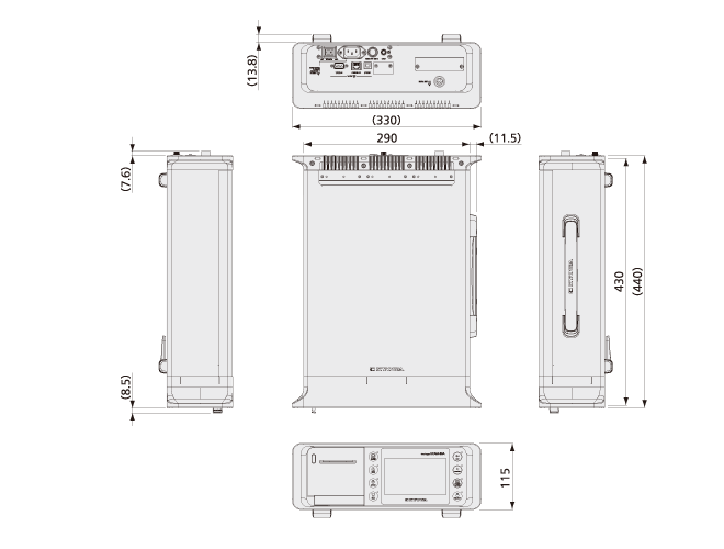
Dimensions |
290(W)× 115(H)× 430(D) mm (Excluding protrusions) |
Weight |
Approx. 6.3 kg (Excluding Scanning Units)
|
Standard Accessories |
AC power cable P-18 (With 2-pin conversion plug CM-52)
|
|---|---|
Optional Accessories |
Dummy Panel UD-80A
|
Dimensions
Specifications
Number of Mountable Units |
3 units can be mounted on UCAM-80A |
|---|---|
Switching Terminal |
Semiconductor Relays |
Channels |
10 / Unit |
Input Terminals |
Connect to lead wire by either soldering of screwing |
Operating Temperature |
0 to 50 °C |
Operating Humidity |
20 to 85% (Non-condensing) |
Dimensions |
320 (W) × 28 (H) × 80 (D) mm (Excluding protrusions) |
Weight |
Approx. 0.8 kg (Including terminal cover) |
Standard Accessories |
Terminal cover 1
|
|---|---|
Optional Accessories |
One-touch terminal block (JT-2A) |
Specifications
Number of Mountable Units |
3 units can be mounted on UCAM-80A |
|---|---|
Switching Terminal |
Semiconductor Relays |
Channels |
10 / Unit |
Input Terminals |
Connect to lead wire by either soldering of screwing
|
Operating Temperature |
0 to 50 °C |
Operating Humidity |
20 to 85% (Non-condensing) |
Dimensions |
320 (W) × 28 (H) × 80 (D) mm (Excluding protrusions) |
Weight |
Approx. 0.9 kg (Including terminal cover) |
Standard Accessories |
Terminal cover 1
|
|---|---|
Optional Accessories |
One-touch terminal block (JT-2A) |
Specifications
Number of Mountable Units |
3 units can be mounted on UCAM-80A |
|---|---|
Switching Terminal |
Semiconductor Relays |
Channels |
10 / Unit |
Input Terminals |
Connect to lead wire by either soldering of screwing |
Operating Temperature |
0 to 50 °C |
Operating Humidity |
20 to 85% (Non-condensing) |
Dimensions |
320 (W) × 28 (H) × 80 (D) mm (Excluding protrusions) |
Weight |
Approx. 0.9 kg (Including terminal cover) |
Standard Accessories |
Terminal cover 1
|
|---|---|
Optional Accessories |
One-touch terminal block (JT-2A) |
Specifications
Measuring Targets |
Strain gages
|
|---|---|
Input Channels |
50/unit |
Connection Data Loggers |
UCAM-80A, UCAM-60C M14, UCAM-65C M14
|
Number of Connection |
Up to 20
|
Input Terminals |
Screw-soldering terminal blocks (M3 screw with washer) |
Channel Mode |
Every channels set by the data logger |
Measuring Channel Number |
The upper 2-digit from every 10 channels are set with digital switches |
Power Supply |
Supplied from data logger.
|
Degrees of Protection |
IP30(JIS C 0920/IEC 60529) |
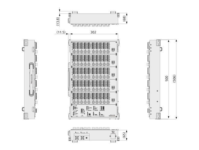
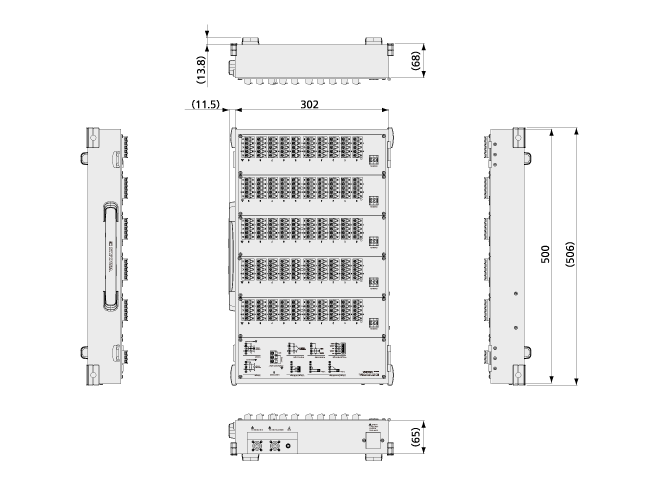
Dimensions |
302(W) × 107(H) × 500(D) mm (Excluding protrusions) |
Weight |
Approx. 7.0 kg (Excluding UPS-80A)
|
Standard Accessories |
Screwdriver 1
|
|---|---|
Option |
Built-in AC Power Unit UPS-80A (100 to 240 VAC 50/60 Hz, Approx. 30 VA)
|
Dimensions

Specifications
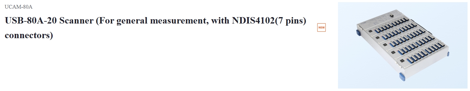
Measuring Targets |
Strain gages
|
|---|---|
Input Channels |
50/unit |
Connection Data Loggers |
UCAM-80A, UCAM-60C M14, UCAM-65C M14
|
Number of Connection |
Up to 20
|
Input Terminals |
Screw-soldering terminal blocks (M3 screw with washer)
|
Channel Mode |
Every channels set by the data logger |
Measuring Channel Number |
The upper 2-digit from every 10 channels are set with digital switches |
Power Supply |
Supplied from data logger.
|
Degrees of Protection |
IP30(JIS C 0920/IEC 60529) |
Dimensions |
302(W) × 107(H) × 500(D) mm (Excluding protrusions) |
Weight |
Approx. 8.0 kg (Excluding UPS-80A)
|
Standard Accessories |
Screwdriver 1
|
|---|---|
Option |
Built-in AC Power Unit UPS-80A (100 to 240 VAC 50/60 Hz, Approx. 30 VA)
|
Dimensions
Specifications
Measuring Targets |
Strain gages
|
|---|---|
Input Channels |
50/unit |
Connection Data Loggers |
UCAM-80A, UCAM-60C M14, UCAM-65C M14
|
Number of Connection |
Up to 20
|
Input Terminals |
Screw-soldering terminal blocks (M3 screw with washer)
|
Channel Mode |
Every channels set by the data logger |
Measuring Channel Number |
The upper 2-digit from every 10 channels are set with digital switches |
Power Supply |
Supplied from data logger.
|
Degrees of Protection |
IP30(JIS C 0920/IEC 60529) |
Dimensions |
302(W) × 107(H) × 500(D) mm (Excluding protrusions) |
Weight |
Approx. 7.3 kg (Excluding UPS-80A)
|
Standard Accessories |
Screwdriver 1
|
|---|---|
Option |
Built-in AC Power Unit UPS-80A (100 to 240 VAC 50/60 Hz, Approx. 30 VA)
|
Dimensions
Specifications
Contact Output |
Alarm signal 4 channels
|
|---|---|
Contact Input |
Start signal 1 channel
|
Pulse Input |
Rainfall signal 1 channel
|
Signal Connection |
D-sub 25-pin connector |
Operating Temperature |
0 to 50 °C |
Operating Humidity |
20 to 85 % (Non-condensing) |
Dimensions |
85 (W) × 23 (H) × 114.1 (D) mm (Excluding protrusions) |
Weight |
Approx. 64 g |
Standard Accessories |
D-sub 25-pin connector XM3A-2521 |
|---|
Specifications
Operating Environment
OS |
Windows🄬 10, Windows🄬 11
|
|---|---|
CPU |
Intel Core i5 2 GHz equivalent or above |
Memory |
32-bit OS: 2 GB or higher
|
Display |
Resolution of 1024 x 768 or above |
Measurement Software
Interfaces
Serial Port |
Use connected over RS-232C. |
|---|---|
LAN Port |
Use connected over Ethernet. |
USB Port |
Use connected over USB. |
Measurement Condition Setting Functions
Controllable Data Logger |
UCAM-80A, UCAM-60C/65C |
|---|---|
Measurement Channel Range |
CH0000 to CH0999 |
Measurement Functions |
Measure value, original value, initial value |
Measurement Count |
0 to 9999 (0: endless) |
Calibration Coefficient Calculation |
ON/OFF setting (all at once) |
Channel Conditions |
Measurement ON/OFF, scanner, measurement channel mode, scanning speed, calibration coefficient, unit, offset, reference resistance, initial value,
|
Interval Measurement Conditions |
Interval measurement start time, interval measurement interval time,
|
Trigger Measurement Conditions |
Trigger channel (any four channels), trigger channel AND/OR, trigger value, reference value, repeat times (0 to 9999 [0: unlimited]), steps (0 to 99) |
Trigger Interval Measurement Conditions |
Trigger channel (any four channels), trigger channel AND/OR, reference value, interval measurement interval time, repeat times (0 to 9999 [0: unlimited]), steps (0 to 99) |
System Control |
Cold junction compensation, power frequency, measurement timing, voltage/temperature initial value subtraction, rainfall input setting possible. |
Alarm Conditions |
Up to four channels, upper/lower limit value setting, hysteresis setting possible. |
Measurement Condition File Operations |
Loading/saving |
Calculation Condition Setting/execution Functions |
Arithmetic operations using channel data can be used.
|
Calculation Condition File Operations |
Loading/saving |
TEDS Compatibility |
TEDS built-in sensor information can be loaded and set to channel conditions. |
Measurement Functions
Measurement check, initial measurement, monitor measurement (max. 50 channels), real-time measurement, automatic measurement (interval measurement, trigger measurement, trigger interval measurement),
|
Measurement Data Numerical Data Display Functions
Numeric window |
Displays measurement data from real-time measurement or automatic measurement |
|---|---|
Display Formats |
Display list 1, display list 2, initial value measurement data display, check result display |
Number of data items that can be displayed in display list 1 |
Most recent 1000 data items |
Monitor window |
Provides summary display of measurement data from monitor measurement
|
Measurement Data Graph Display Functions
Graph Types |
Y-TIME, Y-CYCLE, X-Y graph, BAR graph |
|---|---|
Display Channels |
Max. 20 channels (X-Y graph: max. 10 pairs of channels) |
Number of data items that can be displayed |
Measurement data from real-time measurement or automatic measurement
|
Cursor Display |
Measurement data displayed at cursor position |
Auto Scaling |
Can be auto scaled at X-axis or Y-axis |
Measurement Data Saving
File Formats |
KU1 format, UCAM-70A format (ASCII), CSV format |
|---|---|
File Splitting |
Hourly, daily, per measurement |
Automatic File Conversion |
KU1 format files can be automatically converted to CSV format once measurement is finished. |
Saving to UCAM |
File name, saving location settings |
Dual Display Support |
Numeric window, graph window, or monitor window can be moved to the sub display. |
|---|
Reproduction Software
Data files that can be loaded
KU1 format |
KU1 (KU1 format data files recorded during initial value measurement, real-time measurement, interval measurement, trigger measurement, or trigger interval measurement) |
|---|---|
UCAM-70A format (ASCII) |
INI, RTM, IT1, TRG, T_I |
Measurement Data Display Functions
Measurement Data Numerical Data Display Function |
Display list 1 only |
|---|---|
Measurement Data Graph Display Functions |
Graph types Y-TIME, Y-CYCLE, X-Y graph, BAR graph
|
Display Condition File Operations |
Loading/saving |
Calculation Condition Setting Functions |
Arithmetic operations using channel data can be used.
|
|---|
Calculation Condition Setting Functions
Calculation Condition File Operations |
Loading/saving |
|---|---|
Loading/saving |
Measurement Data Extraction, File Conversion
Can extract measurement data from a given data range or channel range, and convert files to CSV format. |
Measurement Data Combination
Can combine two data files into a single data file. |
Notes: UCS-80A cannot load data files exceeding 2000 channels.The following are limitations when controlling UCAM-60C/65C.EASY MEASURE mode cannot be selected.USB-20/50/51A and USB-65A cannot be used. |