 Contact Sales
  Spec Sheet
 Description
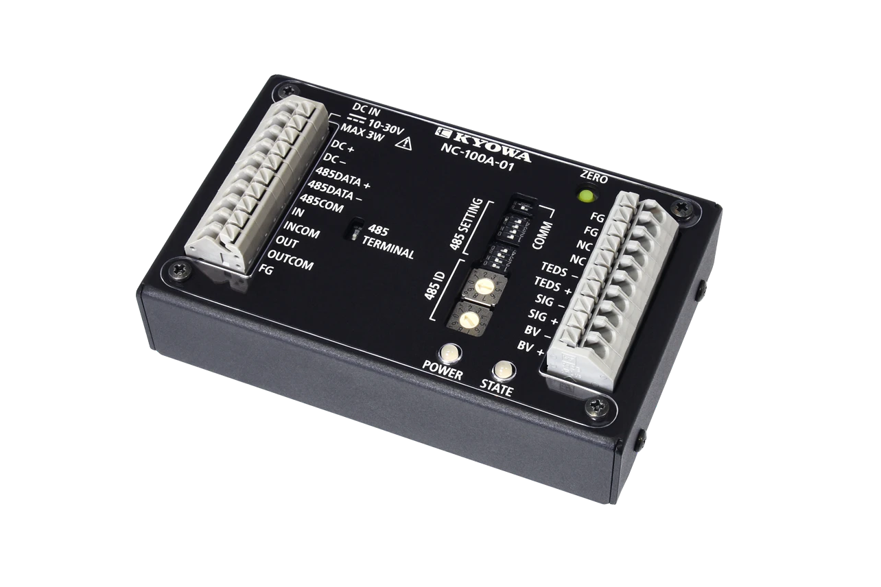
Features
- Easily digitize sensor signals
- Installed near the sensor
- Wide input range (±7.5 mV/V)
- Lightweight (Approx. 100 g)
Specifications
Unit Specifications
Channels |
1 |
|
|---|---|---|
Terminal Block |
One-touch type terminal |
|
Measuring Targets |
Strain-gage transducers |
|
Compatible Bridge Resistance |
350 to 1000 Ω |
|
TEDS |
Interface |
IEEE1451.4 Mixed Mode Transducer Interface Class2 |
Applicable Transducer |
Should have information written in accordance with IEEE template No. 33, cable length should be 30 m or less |
|
Bridge Excitation*1 |
5 VDC ±5% |
|
Measuring Range |
±7.5 mV/V (Input range including zero adjustment range) |
|
Frequency Response |
DC to 200 Hz (±1 dB) |
|
Sampling Speed |
2404 times/s |
|
AD Converter Resolution |
24 bits |
|
Original Value Accuracy*1, *2 |
Within ±0.1% FS |
|
Measure Value Accuracy*1, *2 |
Within ±0.1% FS |
|
Nonlinearity*1, *2 |
Within ±0.1% FS |
|
Control Input |
Points: 1
|
|
Control Output |
Points: 1
|
|
Stability*1 |
TemperatureZero point: Within ±0.4 μVRTI/°C
|
|
Power Supply |
10 to 30 VDC, 3 W or less (24 VDC, 350 Ω load) |
|
Operating Temperature |
-20 to 60°C |
|
Operating Humidity |
20 to 80% (Non-condensing) |
|
Storage Temperature |
-20 to 60°C |
|
Dimensions |
57.4 W × 92.0 D × 20.0 H mm (Excluding protrusions) |
|
Weight |
Approx. 100 g |
|
Vibration Resistance |
29.4 m/s2 (3 G), 5 to 200 Hz (12 cycles for each axis, 10 minutes/cycle) |
|
Shock Resistance |
294 m/s2 (30 G), 11 ms or less, half sine wave |
|
Withstand Voltage |
250 VAC for 1 minute between power supply and sensor input
|
|
Operating Environment |
Indoor use, Pollution degree 2, Altitude up to 2000 m |
|
Degree of Protection |
IP20 (JIS C 0920 / IEC 60529) |
|
Standard Accessories |
Main unit cover
|
|
*1 The measuring unit specifications apply to the state in which the temperature has stabilized after a preheating time of 30 minutes.
*2 Calibration settings rated capacity value 15000, rated output 7.5 mV/V.
*3 It can be downloaded from our website.
Function
Calibration*4 |
Actual load calibration, Sensitivity registering calibration, Numeric value registering calibration, TEDS calibration |
|---|---|
Control*4 |
Zero, Hold, Reset |
Check*4 |
Memory, Bridge excitation, Sensor |
Smoothing*4 |
Moving average:
|
Hold Mode*4 |
Types:
|
Level Test*4 |
Output of arbitrary values possible
|
Comparator*4 |
Compare set values and measured data and output as control output or status.Setting range: ±99999Hysteresis: ON hysteresis, OFF hysteresisHysteresis range: 0 to 99999
|
*4 Set using RS-485 command.
RS-485
Baud Rate |
1200, 2400, 4800, 9600, 19200, 38400, 57600, 115200 bps |
|---|---|
Signal System |
Half duplex system |
Bit Configurations |
Data bits: 7, 8
|
Device ID |
01 to 99 |
Terminating Resistor |
Can be switched using the switch on this unit. |
Optional Accessories |
U-17 S32-7 to 4 conductors with shield wire, bared at the tip (0.5 m)
|
|---|
*5 Remote sensing not supported.
Dimensions

Specifications
Unit Specifications
Channels |
1 |
|
|---|---|---|
Terminal Block |
One-touch type terminal |
|
Measuring Targets |
Strain-gage transducers |
|
Compatible Bridge Resistance |
350 to 1000 Ω |
|
TEDS |
Interface |
IEEE1451.4 Mixed Mode Transducer Interface Class2 |
Applicable Transducer |
Should have information written in accordance with IEEE template No. 33, cable length should be 30 m or less |
|
Bridge Excitation*1 |
5 VDC ±5% |
|
Measuring Range |
±7.5 mV/V (Input range including zero adjustment range) |
|
Frequency Response |
DC to 200 Hz (±1 dB) |
|
Sampling Speed |
2404 times/s |
|
AD Converter Resolution |
24 bits |
|
Original Value Accuracy*1, *2 |
Within ±0.1% FS |
|
Measure Value Accuracy*1, *2 |
Within ±0.1% FS |
|
Nonlinearity*1, *2 |
Within ±0.1% FS |
|
Stability*1 |
TemperatureZero point: Within ±0.4 μVRTI/°C
|
|
Power Supply |
10 to 30 VDC, 3 W or less (24 VDC, 350 Ω load) |
|
Operating Temperature |
-20 to 60°C |
|
Operating Humidity |
20 to 80% (Non-condensing) |
|
Storage Temperature |
-20 to 60°C |
|
Dimensions |
57.4 W × 92.0 D × 20.0 H mm (Excluding protrusions) |
|
Weight |
Approx. 100 g |
|
Vibration Resistance |
29.4 m/s2 (3 G), 5 to 200 Hz (12 cycles for each axis, 10 minutes/cycle) |
|
Shock Resistance |
294 m/s2 (30 G), 11 ms or less, half sine wave |
|
Withstand Voltage |
250 VAC for 1 minute between power supply and sensor input
|
|
Operating Environment |
Indoor use, Pollution degree 2, Altitude up to 2000 m |
|
Degree of Protection |
IP20 (JIS C 0920 / IEC 60529) |
|
Standard Accessories |
Main unit cover
|
|
*1 The measuring unit specifications apply to the state in which the temperature has stabilized after a preheating time of 30 minutes.
*2 Calibration settings rated capacity value 15000, rated output 7.5 mV/V.
*3 It can be downloaded from our website.
Function
Calibration*4 |
Actual load calibration, Sensitivity registering calibration, Numeric value registering calibration, TEDS calibration |
|---|---|
Control*4 |
Zero, Hold, Reset |
Check*4 |
Memory, Bridge excitation, Sensor |
Smoothing*4 |
Moving average:
|
Hold Mode*4 |
Types:
|
Level Test*4 |
Output of arbitrary values possible
|
Comparator*4 |
Compare set values and measured data and output as control output or status.Setting range: ±99999Hysteresis: ON hysteresis, OFF hysteresisHysteresis range: 0 to 99999
|
*4 Set using RS-485 command.
RS-485
Baud Rate |
1200, 2400, 4800, 9600, 19200, 38400, 57600, 115200 bps |
|---|---|
Signal System |
Half duplex system |
Bit Configurations |
Data bits: 7, 8
|
Device ID |
01 to 99 |
Terminating Resistor |
Can be switched using the switch on this unit. |
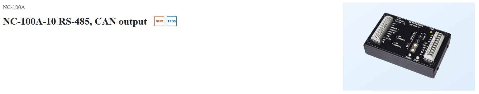
CAN
Baud rate*4 |
10, 20, 25, 33.3, 50, 62.5, 83.3, 100, 125, 250, 500, 1000 kbps |
|---|---|
Output rate*4 |
0.5, 1, 2, 5, 10, 20, 50, 100, 200, 500, 1000 ms |
Data length |
8 bytes (little endian):
|
CAN ID*4 |
Standard format: 0x000 to 0x7FF
|
Terminating resistor |
Can be switched using the switch on this unit. |
*4 Set using RS-485 command.
Optional Accessories |
U-17 S32-7 to 4 conductors with shield wire, bared at the tip (0.5 m)
|
|---|
*5 Remote sensing not supported.
Dimensions
