 Contact Sales
 Description
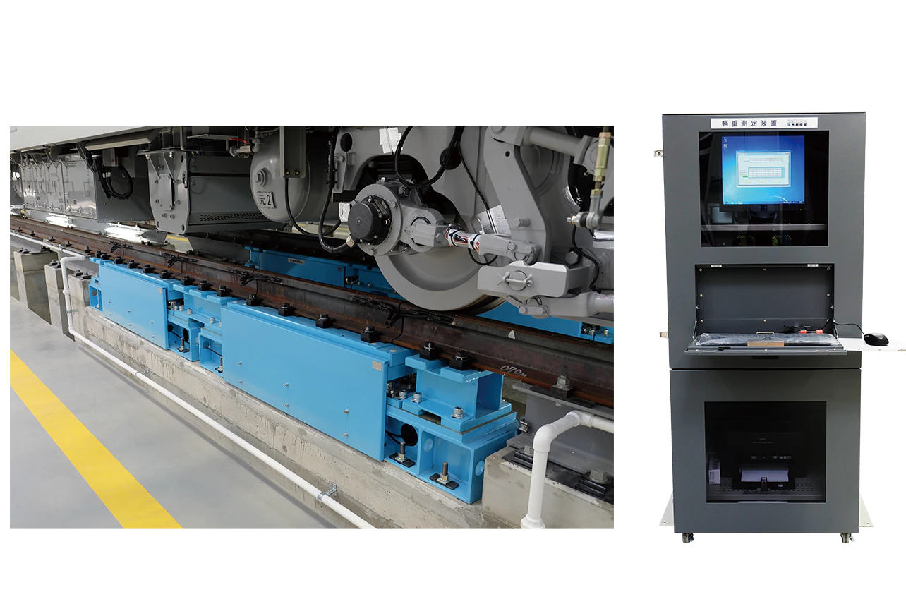
Shearing Strain Gage System
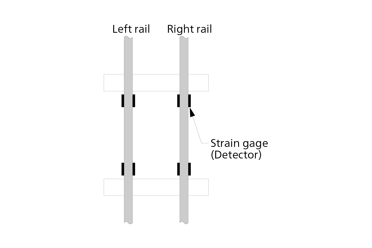
The strain gages are attached directly to the side of the rails, and the wheel load is determined from the shearing strain caused by the wheel load. This system measures the left/right wheel load while the car travels over the rails at a low speed (15 km/h or less) or stops on the rails, with four strain gages attached to both the left and right rails. It is also designed to prevent measurement errors even when unbalanced loads are applied. Output is amplified, undergoes AD conversion, and is captured by a PC, allowing the measurement date/time, wheel load, left/right wheel load ratio, and total weight to be displayed and printed. (Measuring lateral pressure and calculating the derailment coefficient [Q/P] is also available as an option.)
Load Cell System (Ride-Over System)
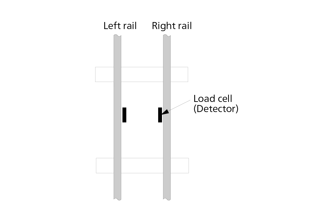
This system measures a car stopped on the rails. It is installed so that the flange edges ride over the load cells, so the detectors can be easily detached and moved for measurement elsewhere. The detector patches can also be removed to allow for normal operation. Installation is easy, and the detectors can even be removed for calibration at the factory. Output is amplified, undergoes AD conversion, and is captured by a PC, allowing the measurement date/time, wheel load, left/right wheel load ratio, and total weight to be displayed and printed.
Load Cell System (Pre-Splitting System)
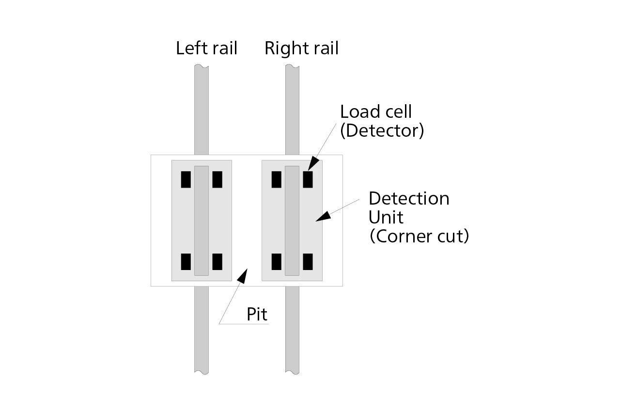
This pit-type system requires the left and right rails to be pre-split approximately 120 cm, with multiple load cells installed underneath to measure wheel load. The measurement stand (sensor) uses four compact load cells and consists of a junction box, data processing system, PC, and printer, allowing for wheel load to be measured accurately. Wheel load output is amplified by a strain amplifier and then captured by a PC through an AD converter, allowing the measurement date/time, wheel load, left/right wheel load ratio, and total weight to be displayed and even printed using a printer.