 Contact Sales
 Description
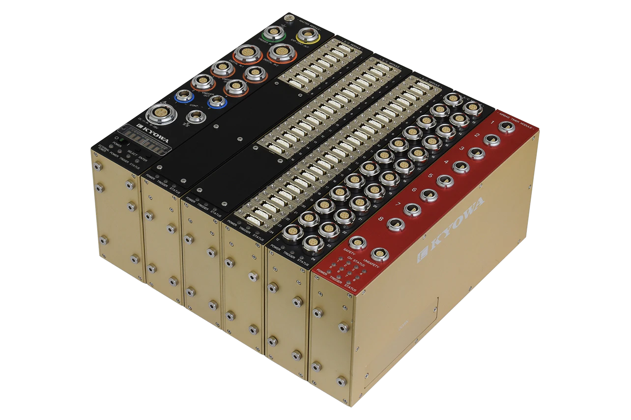
Contents
■Master Module
DIS-7200AS2
■Expansion Modules
DIS-708AS1-T (Signal Conditioner Module, 8 channels)
DIS-716AS1-T (Signal Conditioner Module, 16 channels)
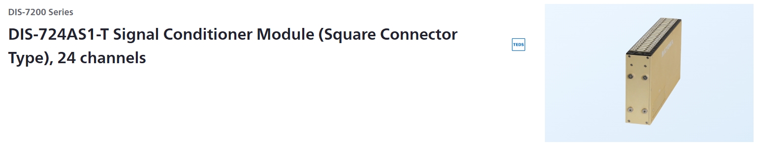
DIS-724AS1-T/L (Signal Conditioner Module, 24 channels)
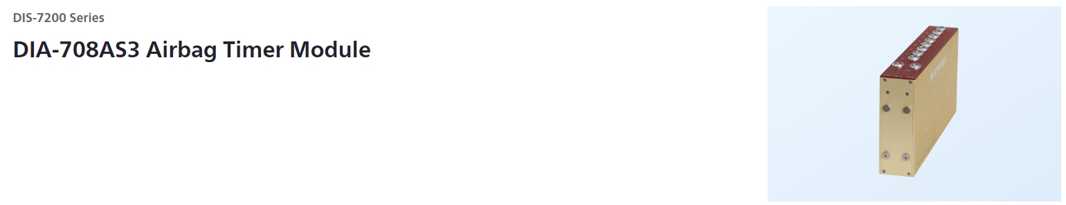
DIA-708AS3 (Airbag Timer Module)
■Control Software
DIS-70A
Block diagrams
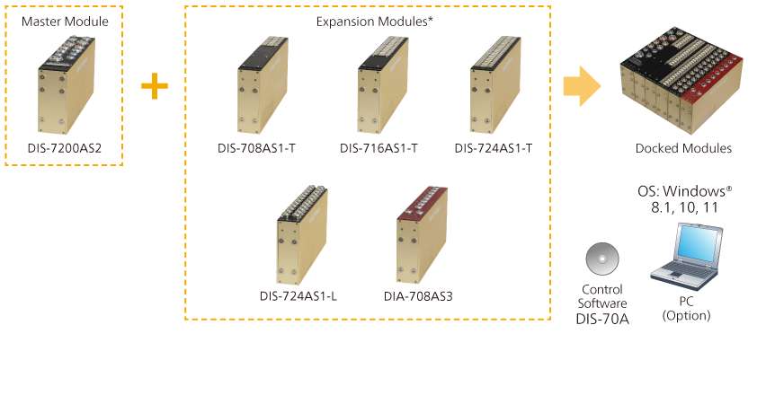
*Up to 15 units are docked per single master module.
*You cannot connect the DIS-7000 Series modules.
Specifications
Expansion Connection
Targets |
Expansion modules of the DIS-7200 series |
|---|---|
Number of Units |
Max. 15 |
Input/Output Connector
LAN Connector |
1 (0B series, LEMO made)
|
|---|---|
[DC=IN] Connector |
1 (2B series, LEMO made)
|
[TRIGGER IN] Connector |
1 (1B series, LEMO made)
|
[CONT.] Connector |
2 (0B series, LEMO made)
|
[EXP. CONT. OUT] Connector |
1 (1B series, LEMO made)
|
[DIGITAL IN 1/2] Connector |
2 (2B series, LEMO made)
|
[TRIGGER OUT] Connector |
4 (1B series, LEMO made)
|
[DOWN] Connector |
1 (D-sub connector, Japan Aviation Electronics Industry, Limited)
|
Switch
[POWER] Switch |
Turns ON/OFF the DIS-7200AS2 and modules, connected to the DIS-7200AS2. |
|---|---|
[SELECT] /[ENTER] Switch |
Selects the LED indicator description. |
LED Indicator/Buzzer
LED |
Status LED |
|---|---|
LED Indicator |
Indicates the DIS-7200AS2 status and modules statuses, connected to the DIS-7200AS2 in 8 alphanumeric. |
Buzzer |
Built-in alarm buzzer |
Status Output |
Connects the external LED unit (optional accessory) for the DIS-7000.
|
|---|
Digital Input
Channels |
16 × 2 (Total 32) |
|---|---|
Input Formats |
Non-voltage contact |
Sampling Method |
All channels synchronization |
Sampling Frequencies |
100, 200, 500, 1 k, 2 k, 5 k, 10 k, 20 k, 50 k, 100 kHz |
Synchronous Operation
Method |
Trigger |
|---|---|
Trigger Type |
Switch Trigger : Non-voltage contact input: 2 (Isolated input)
|
Number of Units |
Max. 48 (Including up to 4 master modules)
|
Connection Method |
[Between Master Modules]Through a cascade cable (Up to 10 m)[Between Master Module (or Expansion Module) and Expansion Module]
|
Data Recorder
Mode |
[Ring buffer mode]
|
|---|---|
Memory Type |
Flash memory |
Memory Capacity |
500 M data/channel |
Recording Time |
Approx. 80 min (at 100 kHz) |
Trigger Distribution Output
Channels |
4 |
|---|---|
Format |
Each channel has the following 3 formats.
|
Timing |
Sets a delay time, required for outputting after recognizing trigger inputs, of each channel. |
Range |
Real time or 0.1 to 9999 ms
|
Accuracy |
Less than 100 ms: Within ±20 μs
|
Check Functions |
Memory check
|
|---|---|
Interfaces |
Conforming to 10BASE-T/100BASE-TX |
Log Function |
Records the DIS-7200AS2 operating statuses (including power supply and trigger). |
Environmental Conditions
Operating Temperature |
0 to 50°C |
|---|---|
Operating Humidity |
20 to 80% (Non-condensing) |
Storage Temperature |
-10 to 60°C |
Storage Humidity |
10 to 90% (Non-condensing) |
Power Supply
Input Range |
15 to 28 VDC (TYP.24 V)
|
|---|---|
Current Consumption |
Max. 300 mA
|
Others |
LED Indicator on the Master Module:
|
Appearance
Dimensions |
Approx. 45 W × 210 D × 100 H mm
|
|---|---|
Weight |
Approx. 1.0 kg |
*Specifications and design are subject to change without notice.
*Please contact us for information on product warranties.
Dimensions
Specifications
Analog Input
Channels |
8 |
|---|---|
Input Connector |
3RT01-RW7F(TAJIMI ELECTRONICS made, applicable plug: 3RT01-PB7M) |
Input Format |
Balanced differential input |
Input Resistance |
Bridge sensor measurement:
|
Input Voltage |
Within ±20 V |
Gain |
×0.1 to 0.9 (× 0.1 step)
|
Gain Accuracy |
Within ±0.2% FS |
Nonlinearity |
Within ±0.1% FS |
Balancing Adjustment |
Gain
|
Bridge Excitation
Voltage Apply Method |
Each channel on/off switchable |
|---|---|
Voltage |
10, 5, 2 VDC
|
Bridge Configuration |
Half bridge system
|
Bridge Resistance |
120 to 5 kΩ |
Current |
Within 30 mA/channel |
LPF
Transfer Characteristic |
5th order Butterworth |
|---|---|
Cutoff Frequencies |
50, 100, 200, 400, 1 k, 2 k, 4 k, 10 k, 20 kHz |
Amplitude Ratio at Cutoff Point |
Within -3 ±1 dB |
Attenuation Characteristic |
Within -30 ±3 dB/oct |
AD Converter
Resolution |
16 bits |
|---|---|
Sampling Method |
All channels synchronization |
Sampling Frequencies |
100, 200, 500, 1 k, 2 k, 5 k, 10 k, 20 k, 50 k, 100 kHz |
S/N Ratio |
50 dB or more (Filter: 1 k Hz) |
Trigger
Type |
Cascade trigger:
|
|---|
Data Recorder
Mode |
Ring buffer mode
|
|---|---|
Memory Type |
Flash memory |
Memory Capacity |
500 M data/channel |
Recording Time |
Approx. 80 min (at 100k Hz) |
TEDS Function |
IEEE1451.4 (Mixed Mode Transducer Interface Class2) supported
|
|---|---|
Check Functions |
Bridge excitation check/sensor check
|
Indicator |
Status LED |
Interface |
Conforming to 10BASE-T/100BASE-TX |
Log Function |
Records the signal conditioner module operating statuses
|
Environmental Conditions
Operating Temperature |
0 to 50°C |
|---|---|
Operating Humidity |
20 to 80% (Non-condensing) |
Storage Temperature |
-10 to 60°C |
Storage Humidity |
10 to 90% (Non-condensing) |
Power Supply
Input Range |
15 to 28 VDC (TYP.24 V)
|
|---|---|
Current Consumption |
Max. 250 mA
|
Applicable Standards |
ISO 6487/SAE J211-1 |
|---|---|
Others |
The signal conditioner module is turned ON/OFF by the master module.
|
Appearance
Dimensions |
Approx. 35 W × 210 D × 100 H mm
|
|---|---|
Weight |
Approx. 0.8 kg |
*Specifications and design are subject to change without notice.
*Please contact us for information on product warranties.
Specifications
Analog Input
Channels |
16 |
|---|---|
Input Connector |
3RT01-RW7F(TAJIMI ELECTRONICS made, applicable plug: 3RT01-PB7M) |
Input Format |
Balanced differential input |
Input Resistance |
Bridge sensor measurement:
|
Input Voltage |
Within ±20 V |
Gain |
×0.1 to 0.9 (× 0.1 step)
|
Gain Accuracy |
Within ±0.2%FS |
Nonlinearity |
Within ±0.1%FS |
Balancing Adjustment |
Gain
|
Bridge Excitation
Voltage Apply Method |
Each channel on/off switchable |
|---|---|
Voltage |
10, 5, 2 VDC
|
Bridge Configuration |
Half bridge system
|
Bridge Resistance |
120 to 5 kΩ |
Current |
Within 30 mA/channel |
LPF
Transfer Characteristic |
5th order Butterworth |
|---|---|
Cutoff Frequencies |
50, 100, 200, 400, 1 k, 2 k, 4 k, 10 k, 20 kHz |
Amplitude Ratio at Cutoff Point |
Within -3 ±1 dB |
Attenuation Characteristic |
Within -30 ±3 dB/oct |
AD Converter
Resolution |
16 bits |
|---|---|
Sampling Method |
All channels synchronization |
Sampling Frequencies |
100, 200, 500, 1 k, 2 k, 5 k, 10 k, 20 k, 50 k,100 kHz |
S/N Ratio |
50 dB or more (Filter: 1 k Hz) |
Trigger
Type |
Cascade trigger:
|
|---|
Data Recorder
Mode |
Ring buffer mode
|
|---|---|
Memory Type |
Flash memory |
Memory Capacity |
500 M data/channel |
Recording Time |
Approx. 80 min (at 100k Hz) |
TEDS Function |
IEEE1451.4 (Mixed Mode Transducer Interface Class2) supported
|
|---|---|
Check Functions |
Bridge excitation check/sensor check
|
Indicator |
Status LED |
Interface |
Conforming to 10BASE-T/100BASE-TX |
Log Function |
Records the signal conditioner module operating statuses
|
Environmental Conditions
Operating Temperature |
0 to 50°C |
|---|---|
Operating Humidity |
20 to 80% (Non-condensing) |
Storage Temperature |
-10 to 60°C |
Storage Humidity |
10 to 90% (Non-condensing) |
Power Supply
Input Range |
15 to 28 VDC (TYP.24 V)
|
|---|---|
Current Consumption |
Max. 350 mA
|
Applicable Standards |
ISO 6487/SAE J211-1 |
|---|---|
Others |
The signal conditioner module is turned ON/OFF by the master module.
|
Appearance
Dimensions |
Approx. 35 W × 210 D × 100 H mm
|
|---|---|
Weight |
Approx. 0.9 kg |
*Specifications and design are subject to change without notice.
*Please contact us for information on product warranties.
Specifications
Analog Input
Channels |
24 |
|---|---|
Input Connector |
EGG.1B.307(LEMO made, applicable plug: FGG.1B.307) |
Input Format |
Balanced differential input |
Input Resistance |
Bridge sensor measurement:
|
Input Voltage |
Within ±20 V |
Gain |
×0.1 to 0.9 (× 0.1 step)
|
Gain Accuracy |
Within ±0.2%FS |
Nonlinearity |
Within ±0.1%FS |
Balancing Adjustment |
Gain
|
Bridge Excitation
Voltage Apply Method |
Each channel on/off switchable |
|---|---|
Voltage |
10, 5, 2 VDC
|
Bridge Configuration |
Half bridge system
|
Bridge Resistance |
120 to 5 kΩ |
Current |
Within 30 mA/channel |
LPF
Transfer Characteristic |
5th order Butterworth |
|---|---|
Cutoff Frequencies |
50, 100, 200, 400, 1 k, 2 k, 4 k, 10 k, 20 kHz |
Amplitude Ratio at Cutoff Point |
Within -3 ±1 dB |
Attenuation Characteristic |
Within -30 ±3 dB/oct |
AD Converter
Resolution |
16 bits |
|---|---|
Sampling Method |
All channels synchronization |
Sampling Frequencies |
100, 200, 500, 1 k, 2 k, 5 k, 10 k, 20 k, 50 k, 100 kHz |
S/N Ratio |
50 dB or more (Filter: 1 kHz) |
Trigger
Type |
Cascade trigger:
|
|---|
Data Recorder
Mode |
Ring buffer mode
|
|---|---|
Memory Type |
Flash memory |
Memory Capacity |
500 M data/channel |
Recording Time |
Approx. 80 min (at 100k Hz) |
TEDS Function |
IEEE1451.4 (Mixed Mode Transducer Interface Class2) supported
|
|---|---|
Check Functions |
Bridge excitation check/sensor check
|
Indicator |
Status LED |
Interface |
Conforming to 10BASE-T/100BASE-TX |
Log Function |
Records the signal conditioner module operating statuses
|
Environmental Conditions
Operating Temperature |
0 to 50°C |
|---|---|
Operating Humidity |
20 to 80% (Non-condensing) |
Storage Temperature |
-10 to 60°C |
Storage Humidity |
10 to 90% (Non-condensing) |
Power Supply
Input Range |
15 to 28 VDC (TYP.24 V)
|
|---|---|
Current Consumption |
Max. 500 mA
|
Applicable Standards |
ISO 6487/SAE J211-1 |
|---|---|
Others |
The signal conditioner module is turned ON/OFF by the master module.
|
Appearance
Dimensions |
Approx. 35 W × 210 D × 100 H mm
|
|---|---|
Weight |
Approx. 1.0 kg |
*Specifications and design are subject to change without notice.
*Please contact us for information on product warranties.
Specifications
Analog Input
Channels |
24 |
|---|---|
Input Connector |
3RT01-RW7F(TAJIMI ELECTRONICS made, applicable plug: 3RT01-PB7M) |
Input Format |
Balanced differential input |
Input Resistance |
Bridge sensor measurement:
|
Input Voltage |
Within ±20 V |
Gain |
×0.1 to 0.9 (× 0.1 step)
|
Gain Accuracy |
Within ±0.2%FS |
Nonlinearity |
Within ±0.1%FS |
Balancing Adjustment |
Gain
|
Bridge Excitation
Voltage Apply Method |
Each channel on/off switchable |
|---|---|
Voltage |
10, 5, 2 VDC
|
Bridge Configuration |
Half bridge system
|
Bridge Resistance |
120 to 5 kΩ |
Current |
Within 30 mA/channel |
LPF
Transfer Characteristic |
5th order Butterworth |
|---|---|
Cutoff Frequencies |
50, 100, 200, 400, 1 k, 2 k, 4 k, 10 k, 20 kHz |
Amplitude Ratio at Cutoff Point |
Within -3 ±1 dB |
Attenuation Characteristic |
Within -30 ±3 dB/oct |
AD Converter
Resolution |
16 bits |
|---|---|
Sampling Method |
All channels synchronization |
Sampling Frequencies |
100, 200, 500, 1 k, 2 k, 5 k, 10 k, 20 k, 50 k,100 kHz |
S/N Ratio |
50 dB or more (Filter: 1 k Hz) |
Trigger
Type |
Cascade trigger:
|
|---|
Data Recorder
Mode |
Ring buffer mode
|
|---|---|
Memory Type |
Flash memory |
Memory Capacity |
500 M data/channel |
Recording Time |
Approx. 80 min (at 100k Hz) |
TEDS Function |
IEEE1451.4 (Mixed Mode Transducer Interface Class2) supported
|
|---|---|
Check Functions |
Bridge excitation check/sensor check
|
Indicator |
Status LED |
Interface |
Conforming to 10BASE-T/100BASE-TX |
Log Function |
Records the signal conditioner module operating statuses
|
Environmental Conditions
Operating Temperature |
0 to 50°C |
|---|---|
Operating Humidity |
20 to 80% (Non-condensing) |
Storage Temperature |
-10 to 60°C |
Storage Humidity |
10 to 90% (Non-condensing) |
Power Supply
Input Range |
15 to 28 VDC (TYP.24 V)
|
|---|---|
Current Consumption |
Max. 500 mA
|
Applicable Standards |
ISO 6487/SAE J211-1 |
|---|---|
Others |
The signal conditioner module is turned ON/OFF by the master module.
|
Appearance
Dimensions |
Approx. 35 W × 210 D × 100 H mm
|
|---|---|
Weight |
Approx. 1.0 kg |
*Specifications and design are subject to change without notice.
*Please contact us for information on product warranties.
Specifications
Ignition Current
Output Channels |
8 |
|---|---|
Connectors |
Mainframe: ECP.0S.302 (LEMO made)
|
Output Current |
Setting range: 0.5 to 3.0 A and OFF (Selectable with 0.1 A steps)
|
Output Voltage |
Approx. 18 V (Max.) |
Load Resistance |
1 to 9 Ω (Including cable resistance value to the inflator)*However, the actual upper limit of the resistance value is obtained from the following.
|
Output Time |
Setting range: 0.2 to 5 ms (Selectable with 0.1 ms)*However,
|
Delay Time |
[Setting range]
|
AD Converter
Resolution |
16 bits |
|---|---|
Measurement Accuracy |
Within ±3%FS (FS = 5.0 A) |
Sampling Method |
All channels synchronization |
Sampling Frequencies |
10 k, 20 k, 50 k, 100 kHz |
Data Recorder
Mode |
[Ring buffer mode]
|
|---|---|
Memory Type |
Flash memory |
Memory Capacity |
250 M data/channel |
Recording Time |
Approx. 40 min (at 100k Hz) |
Trigger
Type |
Cascade triggers:
|
|---|
Check Functions |
Memory check, trigger check, current output check |
|---|
Safety Functions
Safety Functions |
In a state with the SAFETY plug inserted to the SAFETY connector, trigger signals must not be input.
|
|---|---|
Measuring Load Resistence |
Apply weak current (Approx. 10 mA) to the inflator and measure the resistance.
|
CH Status |
Displays the status of the DIA-708AS3 with the LED on the front panel. |
Buzzer |
The built-in buzzer in DIS-7200AS2 issues alarm in the following incident.
|
Interfaces |
Conforming to 10BASE-T/100BASE-TX |
|---|---|
Log Function |
Records the DIA-708AS3 operating statuses (including power supply and trigger). |
Operating Environment
Operating Temperature |
0 to 50 ºC |
|---|---|
Operating Humidity |
20 to 80 % (Non-condensing) |
Storage Temperature |
-10 to 60 ºC |
Storage Humidity |
10 to 90% (Non-condensing) |
Power Supply
Input Range |
15 to 28 VDC (TYP.24 V)
|
|---|---|
Current Consumption |
Max. 250 mA (Power supply: 24 VDC) |
Others |
|
Appearance
Dimensions |
Approx. 35 W × 210 D × 100 H mm
|
|---|---|
Weight |
Approx. 0.9 kg |