 Contact Sales
  Spec Sheet
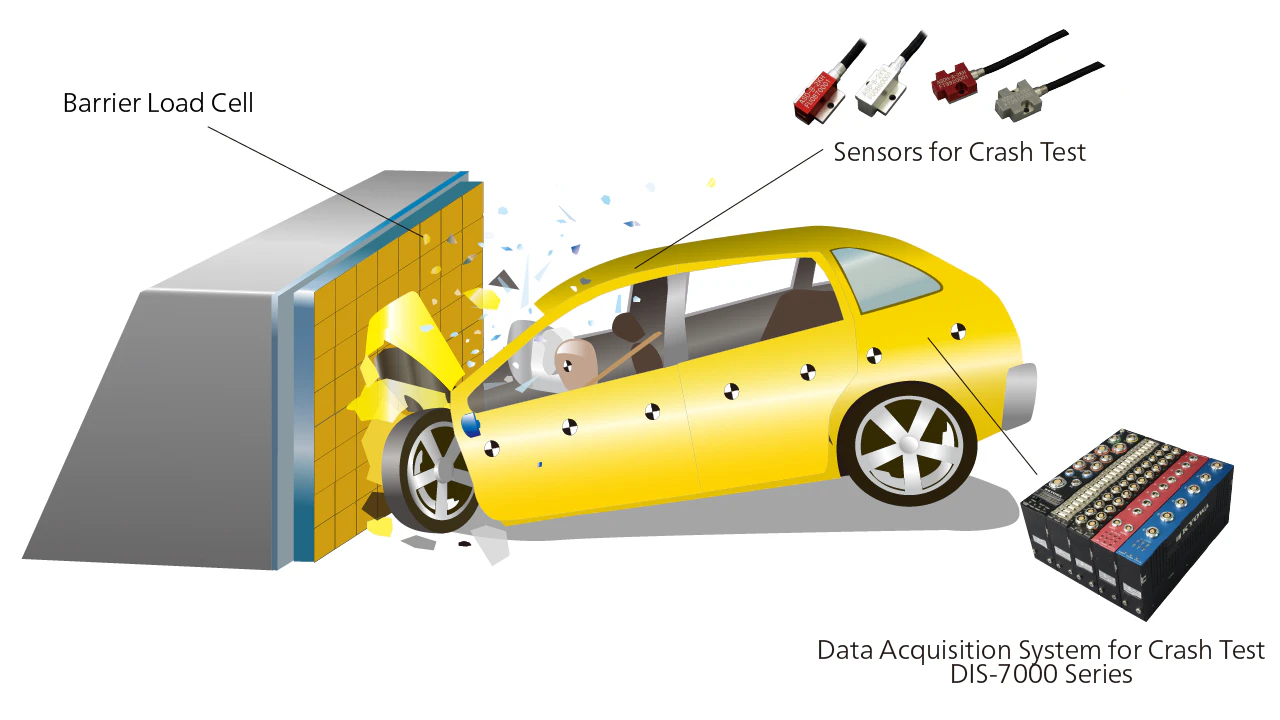
 Description
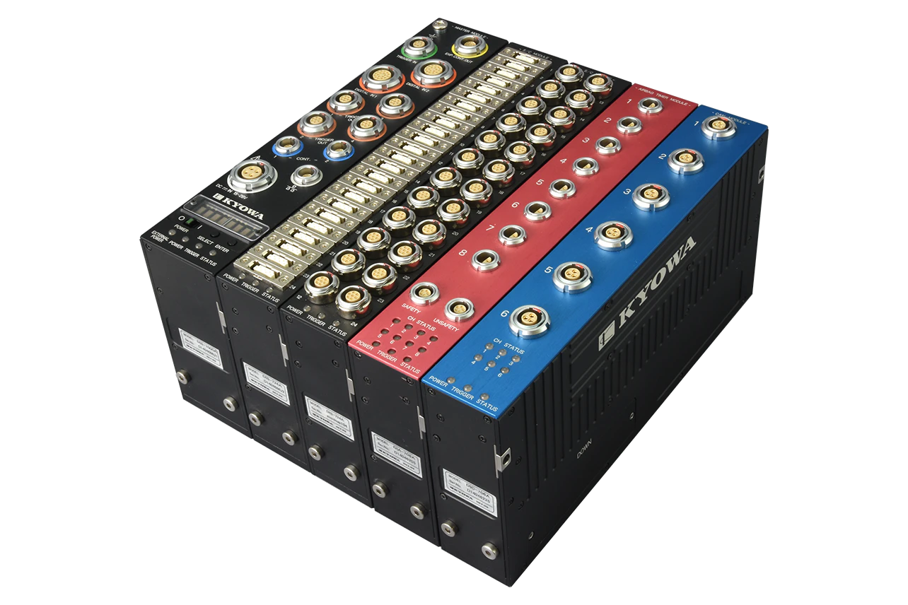
Features
- Multi-channel on-board data logger that can be built for purpose
- Channels: Max. 1056*1
- Impact resistance: 100 G
- CAN/CAN FD data recording compatible (DIC-706B)
*1. Up to 999 channels if using DIS-70A
Contents
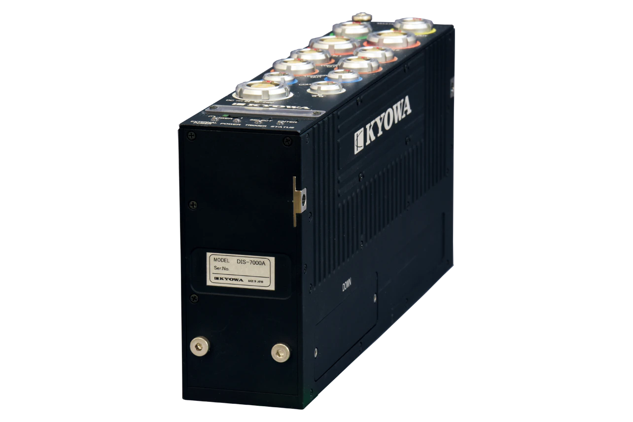
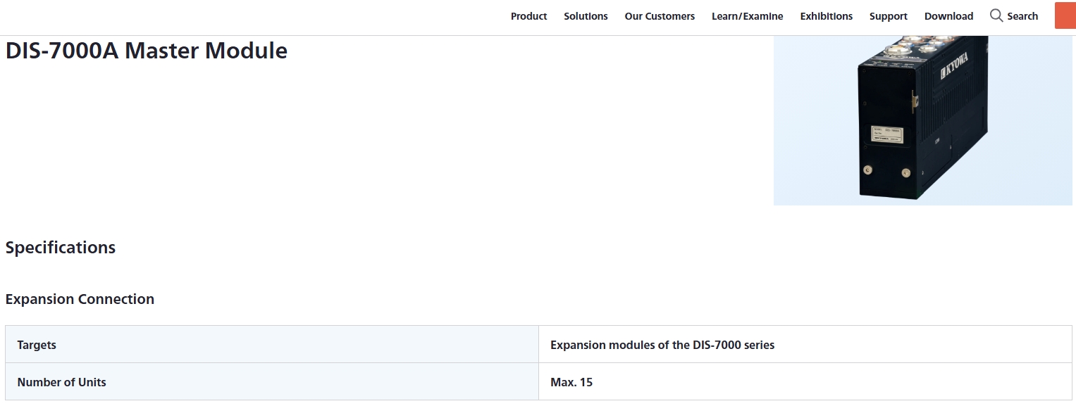
■Master Module
DIS-7000A
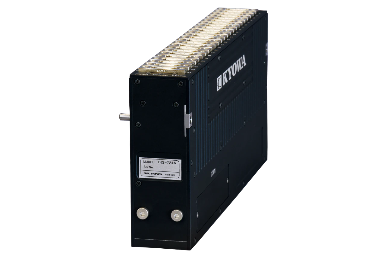
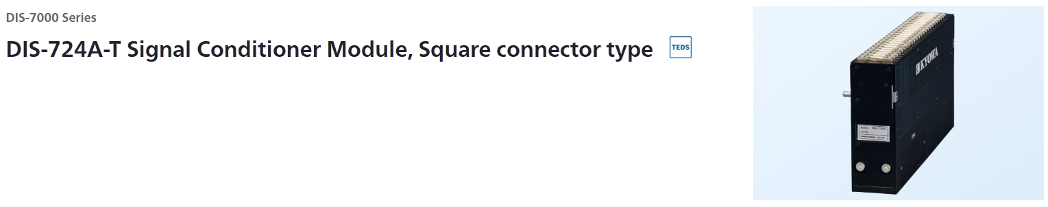
■Expansion Module
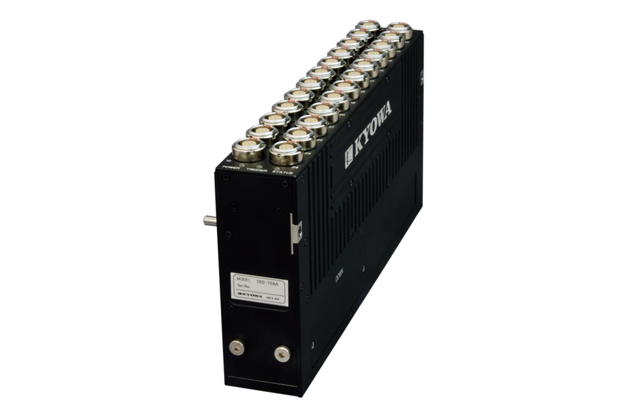
DIS-724A-T/L (Signal Conditioner Module)
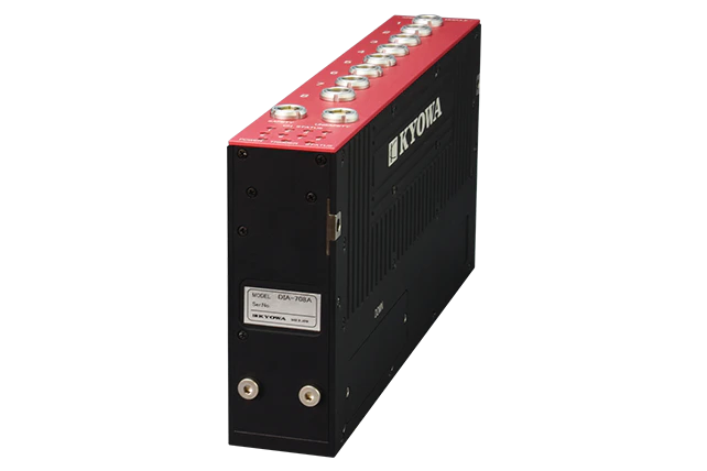
DIA-708A (Airbag Timer Module)
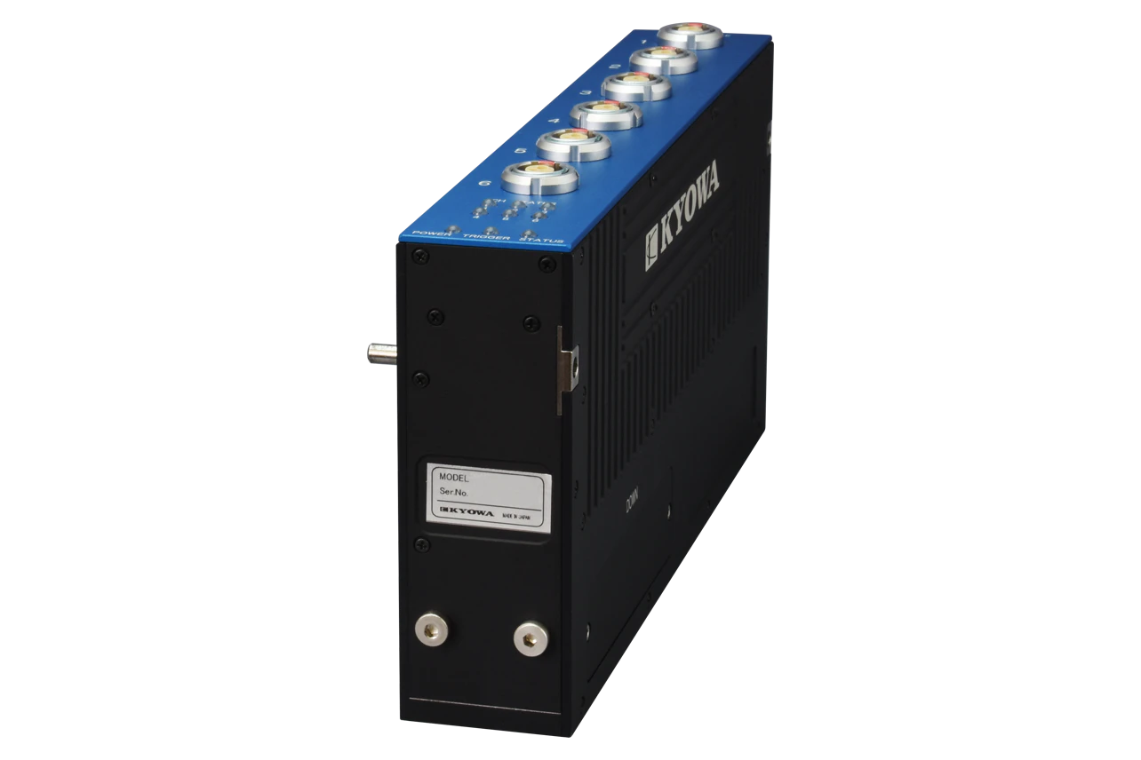
DIC-706B (CAN FD Measurement Module)
■Control Software
DIS-70A
Block diagrams
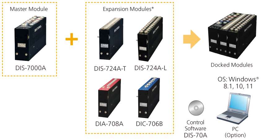
*Up to 15 units are docked per single master module.
Input/Output Connector
LAN Connector |
1 (0B series, LEMO made)
|
|---|---|
[DC=IN] Connector |
1 (2B series, LEMO made)
|
[TRIGGER IN] Connector |
1 (1B series, LEMO made)
|
[CONT.] Connector |
2 (0B series, LEMO made)
|
[EXP. CONT. OUT] Connector |
1 (1B series, LEMO made)
|
[DIGITAL IN 1/2] Connector |
2 (2B series, LEMO made)
|
[TRIGGER OUT] Connector |
4 (1B series, LEMO made)
|
Expansion Connector |
1 (D-sub connector, Japan Aviation Electronics Industry, Limited)
|
*Cables and various devices, connected to the above connectors, are optional accessories.
Switch
[POWER] Switch |
Turns ON/OFF the DIS-7000A and modules, connected to the DIS-7000A. |
|---|---|
[SELECT] /[ENTER] Switch |
Selects the LED indicator description. |
LED Indicator/Buzzer
LED |
Status LED |
|---|---|
LED Indicator |
Indicates the DIS-7000A status and modules statuses, connected to the DIS-7000A in 8 alphanumeric. |
Buzzer |
Built-in alarm buzzer |
Status Output |
Connects the external LED unit (optional accessory) for the DIS-7000A.
|
|---|
Digital Input
Channels |
16 × 2 (Total 32) |
|---|---|
Input Formats |
Non-voltage contact |
Sampling Method |
All channels synchronization |
Sampling Frequencies |
100, 200, 500, 1k, 2k, 5k, 10k, 20k, 50k,100k Hz |
Synchronous Operation
Method |
Trigger |
|---|---|
Trigger Type |
Switch Trigger : Non-voltage contact input: 2 (Isolated input)
|
Number of Units |
Max. 48 (Including up to 4 master modules)
|
Connection Method |
[Between Master Modules]
|
Data Recorder
Mode |
[Ring buffer mode]
|
|---|---|
Memory Type |
Flash memory |
Memory Capacity |
500 M data/channel |
Recording Time |
Approx. 80 min (at 100k Hz) |
Trigger Distribution Output
Channels |
4 |
|---|---|
Format |
Each channel has the following 3 formats.
|
Timing |
Sets a delay time, required for outputting after recognizing trigger inputs, of each channele. |
Range |
Real time or 0.1 to 9999 ms
|
Accuracy |
Less than 100 ms: Within ±20 μs
|
Check Functions |
Memory check
|
|---|---|
Interfaces |
Conforming to 10BASE-T/100BASE-TX |
Log Function |
Records the DIS-7000A operating statuses (including power supply and trigger). |
Environmental Conditions
Operating Temperature |
0 to 50°C |
|---|---|
Operating Humidity |
20 to 80% (Non-condensing) |
Storage Temperature |
-10 to 60°C |
Storage Humidity |
10 to 90% (Non-condensing) |
Impact Resistant |
980.7m/s2 (100 G), 10 ms half-sine
|
Vibration Resistant |
29.4m/s2 (3 G), 5 to 200 Hz
|
Built-in Battery
Type |
Lithium-ion battery |
|---|---|
Chargeable Temperature Range |
5 to 35°C |
Charging Time |
Approx. 3.5 hours (Power OFF, in 10 to 35°C)
|
Continuous Operation Time |
Approx.30 min.
|
-
United Nations Recommendations on the Transport of Dangerous Goods 38.3 tests: Passed
-
IECEE CB Scheme for electrical prodouct safety: Received
Power Supply
Input Range |
15 to 28 VDC (TYP.24 V)
|
|---|---|
Current Consumption |
550 mA
|
Others |
LED Indicator on the Master Module:
|
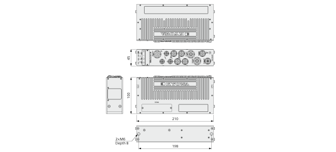
Appearance
Dimensions |
Approx. 45 W × 210 D × 100 H mm
|
|---|---|
Weight |
Approx. 1100 g |
Dimensions
Specifications
Analog Input
Channels |
24 |
|---|---|
Input Connector |
3RT01-RW7F
|
Input Format |
Balanced differential input |
Input Resistance |
Bridge sensor measurement: Approx. (50M + 50 MΩ)Voltage measurement: Approx. (100k +100 kΩ) |
Input Voltage |
Within ±20 V |
Gain |
×0.1 to 0.9 (× 0.1 step)
|
Gain Accuracy |
Within ±0.2%FS |
Nonlinearity |
Within ±0.1%FS |
Balancing Adjustment |
Gain
|
Bridge Excitation
Voltage Apply Method |
Each channel on/off switchable |
|---|---|
Voltage |
10, 5, 2 VDC
|
Bridge Configuration |
Half bridge system
|
Bridge Resistance |
120 to 5 kΩ |
Current |
Within 30 mA/channel |
LPF
Transfer Characteristic |
5th order Butterworth |
|---|---|
Cutoff Frequencies |
50, 100, 200, 400, 1 k, 2 k, 4 k, 10 k, 20 kHz |
Amplitude Ratio at Cutoff Point |
Within -3 ±1 dB |
Attenuation Characteristic |
Within -30 ±3 dB/oct |
AD Converter
Resolution |
16 bits |
|---|---|
Sampling Method |
All channels synchronization |
Sampling Frequencies |
100, 200, 500, 1k, 2k, 5k, 10k, 20k, 50k,100k Hz |
S/N Ratio |
50 dB or more (Filter: 1k Hz) |
Trigger
Type |
[Cascade trigger]
|
|---|
Data Recorder
Mode |
[Ring buffer mode]
|
|---|---|
Memory Type |
Flash memory |
Memory Capacity |
500 M data/channel |
Recording Time |
Approx. 80 min (at 100 k Hz) |
TEDS Function |
IEEE1451.4 (Mixed Mode Transducer Interface Class2) supported
|
|---|---|
Check Functions |
Bridge excitation check
|
Indicator |
Status LED |
Interface |
Conforming to 10BASE-T/100BASE-TX |
Log Function |
Records the DIS-724A operating statuses (including power supply and trigger). |
Environmental Conditions
Operating Temperature |
0 to 50°C |
|---|---|
Operating Humidity |
20 to 80% (Non-condensing) |
Storage Temperature |
-10 to 60°C |
Storage Humidity |
10 to 90% (Non-condensing) |
Impact Resistant |
980.7m/s2 (100 G), 10 ms half-sine
|
Vibration Resistant |
29.4m/s2 (3 G), 5 to 200 Hz
|
Built-in Battery
Type |
Lithium-ion battery |
|---|---|
Chargeable Temperature Range |
5 to 35°C |
Charging Time |
Approx. 3.5 hours (Power OFF, in 10 to 35°C)
|
Continuous Operation Time |
Approx. 30 min
|
-
United Nations Recommendations on the Transport of Dangerous Goods 38.3 tests: Passed
-
IECEE CB Scheme for electrical prodouct safety: Received
Power Supply
Input Range |
15 to 28 VDC (TYP.24 V)
|
|---|---|
Current Consumption |
Max. 800 mA
|
Applicable Standards |
ISO 6487/SAE J211-1 |
|---|---|
Others |
The DIS-724A is turned ON/OFF by the master module.
|
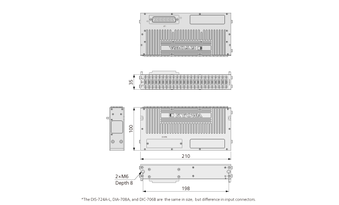
Appearance
Dimensions |
Approx. 35 W × 210 D × 100 H mm
|
|---|---|
Weight |
Approx. 1100 g |
Dimensions
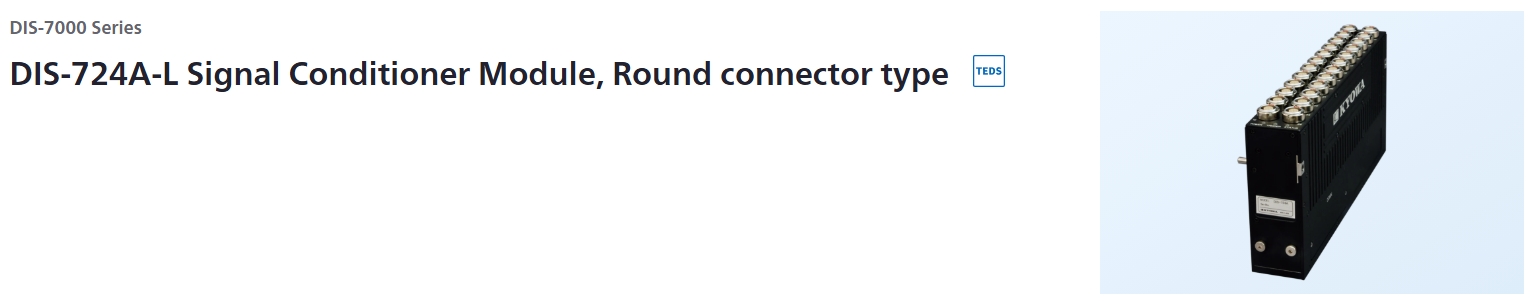
Specifications
Analog Input
Channels |
24 |
|---|---|
Input Connector |
ECG.1B.307
|
Input Format |
Balanced differential input |
Input Resistance |
Bridge sensor measurement: Approx. (50M + 50 MΩ)Voltage measurement: Approx. (100k +100 kΩ) |
Input Voltage |
Within ±20 V |
Gain |
×0.1 to 0.9 (× 0.1 step)
|
Gain Accuracy |
Within ±0.2%FS |
Nonlinearity |
Within ±0.1%FS |
Balancing Adjustment |
Gain
|
Bridge Excitation
Voltage Apply Method |
Each channel on/off switchable |
|---|---|
Voltage |
10, 5, 2 VDC
|
Bridge Configuration |
Half bridge system
|
Bridge Resistance |
120 to 5 kΩ |
Current |
Within 30 mA/channel |
LPF
Transfer Characteristic |
5th order Butterworth |
|---|---|
Cutoff Frequencies |
50, 100, 200, 400, 1 k, 2 k, 4 k, 10 k, 20 kHz |
Amplitude Ratio at Cutoff Point |
Within -3 ±1 dB |
Attenuation Characteristic |
Within -30 ±3 dB/oct |
AD Converter
Resolution |
16 bits |
|---|---|
Sampling Method |
All channels synchronization |
Sampling Frequencies |
100, 200, 500, 1k, 2k, 5k, 10k, 20k, 50k,100k Hz |
S/N Ratio |
50 dB or more (Filter: 1k Hz) |
Trigger
Type |
[Cascade trigger]
|
|---|
Data Recorder
Mode |
[Ring buffer mode]
|
|---|---|
Memory Type |
Flash memory |
Memory Capacity |
500 M data/channel |
Recording Time |
Approx. 80 min (at 100 k Hz) |
TEDS Function |
IEEE1451.4 (Mixed Mode Transducer Interface Class2) supported
|
|---|---|
Check Functions |
Bridge excitation check
|
Indicator |
Status LED |
Interface |
Conforming to 10BASE-T/100BASE-TX |
Log Function |
Records the DIS-724A operating statuses (including power supply and trigger). |
Environmental Conditions
Operating Temperature |
0 to 50°C |
|---|---|
Operating Humidity |
20 to 80% (Non-condensing) |
Storage Temperature |
-10 to 60°C |
Storage Humidity |
10 to 90% (Non-condensing) |
Impact Resistant |
980.7m/s2 (100 G), 10 ms half-sine
|
Vibration Resistant |
29.4m/s2 (3 G), 5 to 200 Hz
|
Built-in Battery
Type |
Lithium-ion battery |
|---|---|
Chargeable Temperature Range |
5 to 35°C |
Charging Time |
Approx. 3.5 hours (Power OFF, in 10 to 35°C)
|
Continuous Operation Time |
Approx. 30 min
|
-
United Nations Recommendations on the Transport of Dangerous Goods 38.3 tests: Passed
-
IECEE CB Scheme for electrical prodouct safety: Received
Power Supply
Input Range |
15 to 28 VDC (TYP.24 V)
|
|---|---|
Current Consumption |
Max. 800 mA
|
Applicable Standards |
ISO 6487/SAE J211-1 |
|---|---|
Others |
The DIS-724A is turned ON/OFF by the master module.
|
Appearance
Dimensions |
Approx. 35 W × 210 D × 100 H mm
|
|---|---|
Weight |
Approx. 1100 g |
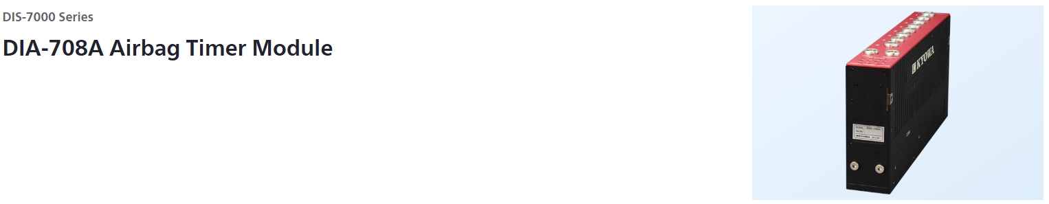
Specifications
Ignition Current
Output Channels |
8 |
|---|---|
Connectors |
Mainframe: ECP.0S.302 (LEMO made)
|
Output Current |
Setting range: 0.5 to 3.0 A and OFF
|
Output Voltage |
Approx. 18 V (Max.) |
Load Resistance |
1 to 9 Ω (Including cable resistance value to the inflator)
|
Output Time |
Setting range: 0.2 to 5 ms (Selectable with 0.1 ms)However, [Example] Accuracy: Within 0.1 ms |
Delay Time |
Setting range:
|
Recording Current Waveform
Resolution |
16 bits |
|---|---|
Measuring Accuracy |
Within ±3%FS (FS = 5.0 A) |
Sampling Method |
All channels synchronization |
Sampling Frequencies |
10k, 20k, 50k, 100k Hz |
Memory |
Memory type: Flash memory
|
Recording Time |
Approx. 40 min (at 100k Hz) |
Trigger
Mode |
Ring buffer mode:
|
|---|---|
Type |
Cascade triggers:
|
Check Functions |
Memory check
|
|---|
Safety Functions
Safety Functions |
In a state with the SAFETY plug inserted to the SAFETY connector, trigger signals must not be input.
|
|---|---|
Load Resistance Measurement |
Apply weak current (Approx. 10 mA) to the inflator and measure the resistance.
|
Resistance measurement before the test |
Just before conducting the test (when moving the SAFETY plug from the SAFETY connector to UNSAFETY connector), automatically measures the load resistance to detect errors such as cable broken. Only when the measured result is within the preset resistance range, the DIA-708A becomes waiting for trigger state to continue the test. |
|---|---|
Resistance measurement after the test |
After completing the ignition, automatically measures the load resistance for detecting the not ignited inflator.The measured resolution is displayed on the status LED on the top face. |
CH Status |
Displays the status of the DIA-708A with the LED on the front panel. |
Buzzer |
The built-in buzzer in DIS-7000A issues alarm in the following incident.
|
Interfaces |
Conforming to 10BASE-T/100BASE-TX |
Log Function |
Records the DIA-708A operating statuses(including power supply and trigger). |
Operating Environment
Operating Temperature |
0 to 50 ºC |
|---|---|
Operating Humidity |
20 to 80 % (Non-condensing) |
Storage Temperature |
-10 to 60 ºC |
Storage Humidity |
10 to 90% (Non-condensing) |
Impact Resistant |
980.7 m/s2 (100 G), 10 ms half-sine
|
Vibration Resistant |
29.4 m/s2 (3 G), 5 to 200 Hz in X, Y, and Z directions, each 10 min/cycle |
Built-in Battery
Type |
Lithium-ion battery |
|---|---|
Chargeable Temperature Range |
5 to 35°C |
Charging Time |
Approx. 3.5 hours (Power OFF, in 10 to 35°C)
|
Continuous Operation Time |
Approx. 30 min
|
-
United Nations Recommendations on the Transport of Dangerous Goods 38.3 tests: Passed
-
IECEE CB Scheme for electrical prodouct safety: Received
Power Supply
Input Range |
15 to 28 VDC (TYP.24 V)
|
|---|---|
Current Consumption |
Max. 550 mA
|
| Others | The DIA-708A is turned ON/OFF by the master module. External power supply: Kyowa’s recommended external power supply only |
|---|---|
| Dimensions | Approx. 35 W × 210 D × 100 H mm (Excluding protrusions and options.) |
| Weight | Approx. 1000 g |
*Specifications and design are subject to change without notice.
*Please contact us for information on product warranties.
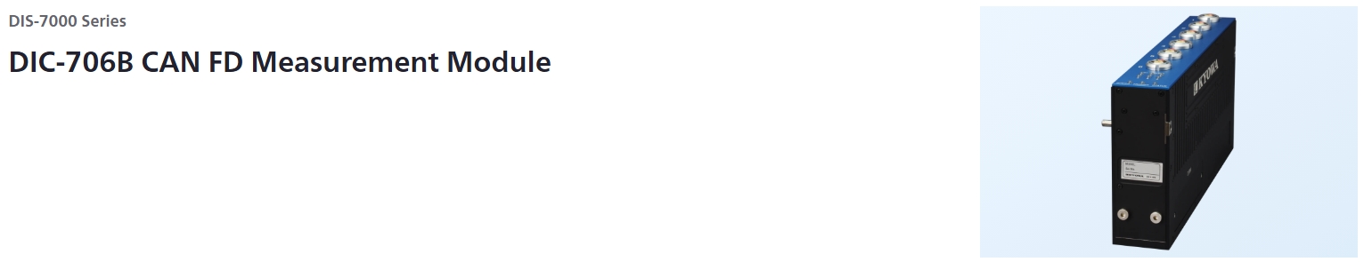
Specifications
CAN
Channels |
6 |
|---|---|
Connector Type |
ECB.1B.303 (LEMO made., applicable plug: FGB.1B.303) |
Physical Layer |
High speed CAN |
Isolation |
Every Channel |
CAN Controller |
CAN FD supported (ISO/ DIS 11898-1) |
Nominal Bit Rate |
1000, 800, 500, 250, 125 kbps |
Data Bit Rate |
5, 4, 2, 1, 0.5 Mbps*
|
Terminator |
Select ON/OFF |
Listen Only Mode |
Select ON/OFF |
Recording CAN Data
Frame To Record |
Data frame (CAN Identifier and Data only) |
|---|---|
Recording Mode |
Dump mode (All CAN ID on the CAN bus is recorded.)
|
Sampling Method |
Recording CAN (FD) data with timestamp added |
Timestamp Resolution |
0.1, 0.05, 0.02, 0.01 ms |
Memory Type |
Flash memory |
Memory Capacity |
Approx. 200 Mega Frames (6 Channels total) |
Recording Time |
Depends on frame quantity and channel number*For example, When 6 Channel measurement is performed on CAN ID type number 100 and frame output cycle 10 ms, since the number of frames received per second is 60000 frames in total of 6 Channel, 200 Mega / 60000 = recording time about 55 min. |
Sending CAN Data |
Data frames of arbitrary CAN ID and Data can be instantly output to arbitrary Channel by control command. |
|---|
Trigger
Mode |
Ring buffer mode:
|
|---|---|
Type |
Cascade trigger:
|
Check Function |
|
|---|
Channel Status/ Buzzer
Chanel Status |
Displays the status of the DIC-706B with the LED on the panel face. |
|---|---|
Buzzer |
The buzzer which a DIS-7000A has built-in issues alarm in the following incident.
|
Interface |
Conforming to 10BASE-T/100BASE-TX. |
|---|---|
Log Function |
Records the DIC-706B operating statuses (Including power supply and trigger). |
Environmental Conditions
Operating Temperature |
0 to 50°C |
|---|---|
Operating Humidity |
20 to 80% (Non-condensing) |
Storage Temperature |
-10 to 60°C |
Storage Humidity |
10 to 90% (Non-condensing) |
Impact Resistance |
980.7 m/s2 (100 G), 10 ms, half-sine
|
Vibration Resistance |
29.4 m/s2 (3 G), 5 to 200 Hz
|
Built-in Battery
Type |
Lithium-ion battery |
|---|---|
Chargeable Temperature |
5 to 35°C |
Charging Time |
Approx. 3.5 h (Power: OFF, operating temperature: 10 to 35°C)
|
Continuous Operation Time |
Approx. 30 min (Operating temperature: 0 to 40°C, non degradation) |
-
United Nations Recommendations on the Transport of Dangerous Goods 38.3 tests: Passed
-
IECEE CB Scheme for electrical prodouct safety: Received
Power Supply
Input Range |
15 to 28 VDC (TYP.24 V)*Make sure the external power supply (Optional accessory) is 24 VDC. |
|---|---|
Current Consumption |
Max. 480 mA (Power supply: 24 V) |
Others |
The DIC-706B is turned ON/OFF by the master module.
|
|---|
Appearance
Dimensions |
Approx. 35 W × 210 D × 100 H mm
|
|---|---|
Weight |
Approx. 0.9 kg |