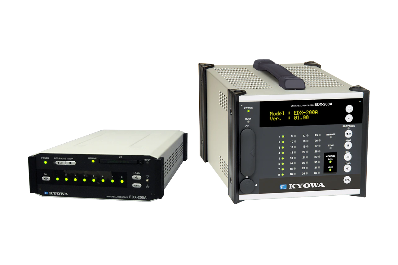
Description
To Ensure Proper Usage
- When performing arithmetic operations using EDX-200A and DCS-101A, CAN measurements via option cards cannot be performed simultaneously.
- When dual sampling mode is turned ON, you can select from three types in the channel condition settings of the control software: High-speed, Low- speed, and High-speed + Low-speed. Channels set to High-speed + Low-speed are counted as two channels.
Remarks
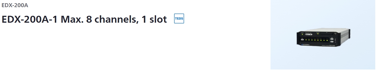
- EDX-200A-1 has different functions from other models.
- EDX-200A-4T can use only conditioner card and optional card which performed temperature extension processing.
- DCS-100A is optional for models with suffix “-0”. Models with suffix “-1” come with DCS-101A.
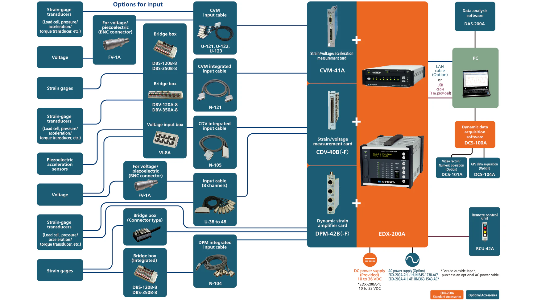
Simplified configuration of the EDX-200A
Specifications
Models
|
EDX-200A-1 (With DCS-100A)
EDX-200A-1-1 (With DCS-100A and DCS-101A)
|
Measuring Targets
|
Strain (Gage, transducer)
Voltage
Thermocouples
Pulse (F/V)
Piezoelectric acceleration (Built-in amplifier)
CAN signals
GPS
|
Conditioner Cards
for Analog Inputs
|
The conditioner cards for EDX series
[Note] The EDX-200A-4T can use only the CVM-41A,CDV-40B, CDV-40B-F and CAN-41A which performed temperature extension processing.
[Note] The EDX-200A limits the number of CFV-40A.
The number of CFV-40A is up to 1.
|
Conditioner Cards for CAN Data Inputs
|
CAN card (2 ports, max. 256 channels): CAN-41A
[Note] Can install one CAN-41A to the final slot.
|
Voice Memo Input
|
1 channel
(Input voice memo data is recorded together with the measurement data.)
Use remote control unit RCU-42A. (Optional accessory)
Use the Data Analysis Software DAS-200A (optional accessory) to play back recorded voice memos.
|
Sampling
Sampling Method
|
Simultaneously all channels
|
Sampling Mode
|
Normal: Records all channels’ data at the same sampling clock.
Dual: Enables high-speed sampling or low-speed sampling to every CH for recording.
|
Sampling Frequencies
Normal-sampling Mode
|
1-2-5 series
1 Hz to 100 kHz
1 Hz to 2 kHz When using CAN-41A2n series
2 to 65536 Hz
2 to 2048 Hz When using CAN-41A
|
Dual-sampling Mode
|
High-speed sampling [Sf]
1-2-5 series
1 Hz to 100 kHz
1 Hz to 2 kHz when using CAN-41A
2n series
2 to 65536 Hz
2 to 2048 Hz when using CAN-41ALow-speed sampling [Ss]
1-2-5 series
The division frequencies from
high-speed sampling, and Ss ≤ Sf/4
2n series
The division frequencies from
high-speed sampling, and Ss ≤ Sf/4
|
Channels
Normal-sampling Mode
|
Max. 32 channels, 320 k/I (I is the integer part of the set sampling frequency.)
|
Dual-sampling Mode
|
Max. 64 channels, 320 k/I (I is the integer part of the set sampling frequency.). “High-speed and low-speed” setting counts as 2 channels.
|
When Using CAN-41A
|
Channels of CAN data
|
The Number of Sampling Frequency
Normal Mode
|
“320000/ The number of channels” or less
|
Dual Mode
|
High-speed sampling frequency:
“320000/ The number of channels” or less.*About high-speed and low-speed setting channels, the number of channels per channel is 2.
|
Digital Filter
|
Butterworth filter (IIR)
Type of filter: LPF, HPF
Order of a filter: 1 to 8
Amplitude ratio at cutoff point: -3 dB
Attenuation: -6 x N dB/oct. (N is order of the filter)*Simultaneously use with built-in LPF possible.
*Application on CAN data not possible.
|
Data Recording Unit
|
CF card
Capacity: 128 MB to 16 GB (our recommended only)
Maximum data file size (available data file size to be recorded)
When the number of repeat times is 1: 4 GB/data file
When the number of repeat times is 2: 1 GB/data file
(1GB = 1000000000 bytes)
|
Control Switch
|
UP/DOWN : Changes the display on the small indicator.
REC/PAUSE : Starts and pauses data recording.
STOP : Stops data recording.
BAL. : Execute the balance.
LOAD : Loads and sets conditions.
OPT. : Conducts the pre-set arbitrary function.
ID : Sets the EDX-200A identification No.
POWER : POWER switch
USB/LAN : Selects a communication interface (USB /LAN)
[NOTE] The EDX-200A-1 does not have the UP/DOWN switch and ID switch.
|
Indicator
|
Channel status display LED: 8
Unit status display LED: 4
|
Operating Switch
|
REC/PAUSE: Start/pause data recording.
STOP: Stop data recording.
BAL.: Implement balance (Balance adjustment)
LOAD: Read and configure conditions from CF card
OPT.: Execute arbitrary configured functions
POWER: Power switch
USB/LAN: Communications I/F, switchable
|
External Control Connector
|
CONT. IN
(Remote control, for synchronous operation)
|
Communication interfaces
|
USB(USB2.0 High Speed) 1 port
Connector: Series B receptacle connector
LAN(10/100BASE-T) 2 ports
LAN IN connector: For PC communication
LAN OUT connector For synchronous operation
Connector: RJ45 modular jack connector
[NOTE] The EDX-200A-1 does not have the LAN OUT connector for the synchronous operation.
|
How To Setting Conditions
|
Online setting: Set measuring conditions on the PC via the LAN or USB
interface.
Offline setting: Set measuring conditions by allowing the EDX-200A to
read measuring conditions in the CF card. (Use DCS-100A to set measuring conditions.)
|
Saving Conditions
|
Store the conditioner cards’ setting conditions and measuring conditions in nonvolatile memory in the EDX-200A.
When turning ON the EDX-200A, the user can immediately start data recording with previously set conditions.
|
Measuring Modes
|
Manual measurement
Trigger measurement
Interval measurement
|
Manual Measurement
|
Data recording is manually started or stopped when data is recorded to a preset number of measured data.
Manual mode allows recording of voice memo during data recording.
|
Trigger Measurement
|
Data recording is automatically started when the preset trigger condition is satisfied.
*No CAN data of CAN-41A is used as the trigger condition.
|
Interval Measurement
|
Automatically recording functions based upon previously-set interval conditions
Combination with measured mode when in dual sampling
(High-speed sampling channel – Low-speed sampling channel)
Manual——————————–Manual
Trigger——————————–Manual, interval
Interval —————————— Interval
|
Starting and Stopping Data Recording
|
Data recording starts/stops by using the PC,panel switches or the RCU-42A
|
Balance Operation
|
Adjust the balance of the strain input channel and conduct the zero suppress of the voltage input CH of the CVM-41A by using the PC, control switches (on the front panel) or the RCU-42A
|
Recording Data Format
|
Kyowa standard file format KS2
Analysis using optional Data Analysis Software DAS-200A is possible.
|
Data Collection
|
Online using PC, or offline direct reading from CF card to PC
|
TEDS Function
|
TEDS function is available only when online control from the PC.
TEDS compatible conditioner cards: CDV-40B (-F),DPM-42B (-F), DPM-42B-I (-F), CCA-40A (-F),CDV-44AS, CDA-44AS, CDA-45AS, CVM-41A
|
Power Supply
|
10 to 33 VDC
Connector type: RM12BRD-4PH (Hirose)
Use DC power supply or AC adapter (Optional accessory)
|
Current Consumption
|
Approx. 1.0 A
(12 VDC with 1 CDV-40B card installed)
|
Operating Temperature
|
0 to 50ºC
|
Operating Humidity
|
20 to 90% (Non-condensing)
|
Storage Temperature
|
−20 to 60ºC
|
Vibration Resistant
|
49.0 m/s2 (5 G), 5 to 55 Hz 1 cycle 1 min., each axis 15 cycles
(Non-operating)29.4 m/s2 (3 G), 5 to 55 Hz 1 cycle 1 min., each axis 15cycles
(Operating)
|
Impact Resistant
|
294.2 m/s2 (30 G) /11 ms
|
Dimensions
|
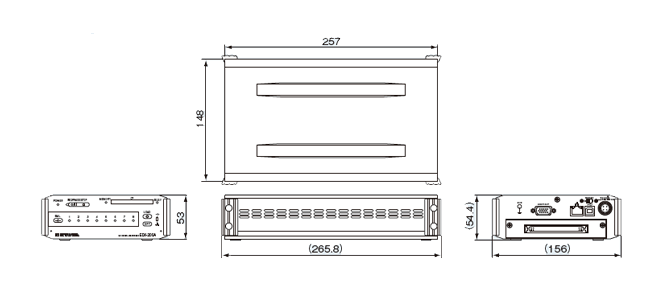
148 W x 53 H x 257 D mm (Excluding protrusions)
|
Weight
|
Approx. 0.9 kg (Approx.1.1 kg with 1 CDV-40B cards installed.)
|
Compliance
|
Directive 2014/30/EU (EMC)
Directive 2011/65/EU, (EU)2015/863
(10 restricted substances) (RoHS)
|
Standard Accessories
|
DC power cable P-76
USB cable N-38
Ground wire P-72
CF card (1 GB) inserted in the slot
EDX accessory bag
Dynamic data acquisition software DCS-100A (DVD)
*DCS-100A is optional for models with suffix -0.
Instruction manual (In English & Japanese, in the above DVD)
|
Optional Accessories
|
AC adapter UNI345-1238-AC
Fixing adapter
EDX dummy panel EDX1P-DUMMY
Remote control unit RCU-42A
Monitor unit EMON-20A
|
Specifications
Models
|
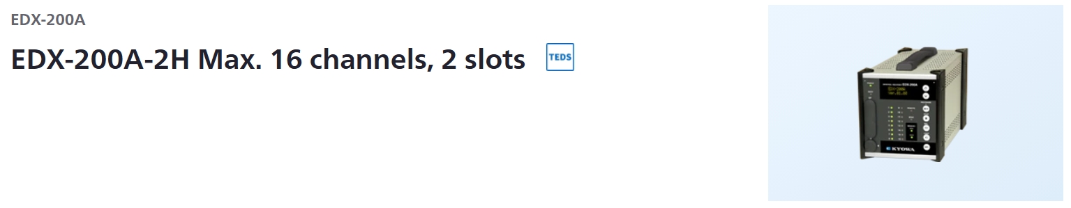
EDX-200A-2H (With DCS-100A)
EDX-200A-2H-0
EDX-200A-2H-1 (With DCS-100A and DCS-101A)
|
Measuring Targets
|
Strain (Gage, transducer)
Voltage
Thermocouples
Pulse (F/V)
Piezoelectric acceleration (Built-in amplifier)
CAN signals
GPS
|
Conditioner Cards for Analog Inputs
|
The conditioner cards for EDX series
[Note] The EDX-200A-4T can use only the CVM-41A,CDV-40B, CDV-40B-F and CAN-41A which performed temperature extension processing.
[Note] The EDX-200A limits the number of CFV-40A.
The number of CFV-40A is up to 1.
|
Conditioner Cards for CAN Data Inputs
|
CAN card (2 ports, max. 256 channels): CAN-41A
[Note] Can install one CAN-41A to the final slot.
|
Voice Memo Input
|
1 channel
(Input voice memo data is recorded together with the measurement data.)
Use remote control unit RCU-42A. (Optional accessory)
Use the Data Analysis Software DAS-200A (optional accessory) to play back recorded voice memos.
|
Sampling
Sampling Method
|
Simultaneously all channels
|
Sampling Mode
|
Normal: Records all channels’ data at the same sampling clock.
Dual: Enables high-speed sampling or low-speed sampling to every CH for recording.
|
Sampling Frequencies
Normal-sampling Mode
|
1-2-5 series
1 Hz to 100 kHz
1 Hz to 2 kHz When using CAN-41A
2n series
2 to 65536 Hz
2 to 2048 Hz When using CAN-41A
|
Dual-sampling Mode
|
High-speed sampling [Sf]
1-2-5 series
1 Hz to 100 kHz
1 Hz to 2 kHz when using CAN-41A
2n series
2 to 65536 Hz
2 to 2048 Hz when using CAN-41A
Low-speed sampling [Ss]
1-2-5 series
The division frequencies from
high-speed sampling, and Ss ≤ Sf/4
2n series
The division frequencies from
high-speed sampling, and Ss ≤ Sf/4
|
Channels
Normal-sampling Mode
|
Max. 32 channels, 320 k/I (I is the integer part of the set sampling frequency.)
|
Dual-sampling Mode
|
Max. 64 channels, 320 k/I (I is the integer part of the set sampling frequency.). “High-speed and low-speed” setting counts as 2 channels.
|
When Using CAN-41A
|
Channels of CAN data
|
The Number of Sampling Frequency
Normal Mode
|
“320000/ The number of channels” or less
|
Dual Mode
|
High-speed sampling frequency:
“320000/ The number of channels” or less.
*About high-speed and low-speed setting channels, the number of channels per channel is 2.
|
Digital Filter
|
Butterworth filter (IIR)
Type of filter: LPF, HPF
Order of a filter: 1 to 8
Amplitude ratio at cutoff point: -3 dB
Attenuation: -6 x N dB/oct. (N is order of the filter)
*Simultaneously use with built-in LPF possible.
*Application on CAN data not possible.
|
Data Recording Unit
|
CF card
Capacity: 128 MB to 16 GB (our recommended only)
Maximum data file size (available data file size to be recorded)
When the number of repeat times is 1: 4 GB/data file
When the number of repeat times is 2: 1 GB/data file
(1GB = 1000000000 bytes)
|
Control Switch
|
UP/DOWN : Changes the display on the small indicator.
REC/PAUSE : Starts and pauses data recording.
STOP : Stops data recording.
BAL. : Execute the balance.
LOAD : Loads and sets conditions.
OPT. : Conducts the pre-set arbitrary function.
ID : Sets the EDX-200A identification No.
POWER : POWER switch
USB/LAN : Selects a communication interface (USB /LAN)
[NOTE] The EDX-200A-1 does not have the UP/DOWN switch and ID switch.
|
Indicator
|
Channel status display LED: 16
Unit status display LED: 7
Unit status display organic EL monitor: 1
|
Operating Switch
|
UP, DOWN: Status display organic EL monitor display switching
REC/PAUSE: Start/pause data recording.
STOP: Stop data recording.
BAL.: Implement balance (Balance adjustment)
LOAD: Read and configure conditions from CF card
OPT.: Execute arbitrary configured functions
ID: EDX identifier configuration
POWER: Power switch
USB/LAN: Communications I/F, switchable
|
External Control Connector
|
CONT IN, CONT OUT
(Remote control, for synchronous operation)
|
Communication interfaces
|
USB(USB2.0 High Speed) 1 port
Connector: Series B receptacle connector
LAN(10/100BASE-T) 2 ports
LAN IN connector: For PC communication
LAN OUT connector For synchronous operation
Connector: RJ45 modular jack connector
|
Synchronous Operation
|
Max. 8 EDX-200A units can be connected for synchronous operation by using synchronous cables N-95 N-128.
Max. 8 EDX-200A units can be connected for synchronous operation by using LAN cables.
[NOTE] The synchronous operation is not available with the EDX-200A-1.
|
How To Setting Conditions
|
Online setting: Set measuring conditions on the PC via the LAN or USB
interface.
Offline setting: Set measuring conditions by allowing the EDX-200A to
read measuring conditions in the CF card. (Use DCS-100A to set measuring conditions.)
|
Saving Conditions
|
Recording of conditioner configuration conditions and measurement conditions within the EDX built-in nonvolatile memory.
Immediate start of data collection using the previously configured measurement conditions after power-on is possible.
|
Measuring Modes
|
|
Manual measurement
Trigger measurement
Interval measurement
|
Manual Measurement
|
Data recording is manually started or stopped when data is recorded to a preset number of measured data.
Manual mode allows recording of voice memo during data recording.
|
Trigger Measurement
|
Data recording is automatically started when the preset trigger condition is satisfied.
*No CAN data of CAN-41A is used as the trigger condition.
|
Interval Measurement
|
Automatically recording functions based upon previously-set interval conditions
Combination with measured mode when in dual sampling
(High-speed sampling channel – Low-speed sampling channel)
Manual——————————–Manual
Trigger——————————–Manual, interval
Interval —————————— Interval
|
Starting and Stopping Data Recording
|
Data recording starts/stops by using the PC,panel switches or the RCU-42A
|
Balance Operation
|
Adjust the balance of the strain input channel and conduct the zero suppress of the voltage input CH of the CVM-41A by using the PC, control switches (on the front panel) or the RCU-42A
|
Recording Data Format
|
Kyowa standard file format KS2
Analysis using optional Data Analysis Software DAS-200A is possible.
|
Data Collection
|
Online using PC, or offline direct reading from CF card to PC
|
TEDS Function
|
TEDS function is available only when online control from the PC.
TEDS compatible conditioner cards: CDV-40B (-F),DPM-42B (-F), DPM-42B-I (-F), CCA-40A (-F),CDV-44AS, CDA-44AS, CDA-45AS, CVM-41A
|
Power Supply
|
10 to 36 VDC
Connector type: RM12BRD-4PH (Hirose)
Use DC power supply or AC adapter (Optional accessory)
|
Current Consumption
|
Approx. 1.6 A(12 VDC with 2 CDV-40B card installed)
|
Operating Temperature
|
0 to 50ºC
|
Operating Humidity
|
20 to 90% (Non-condensing)
|
Storage Temperature
|
-20 to 60ºC
|
Vibration Resistant
|
49.0 m/s2 (5 G), 5 to 55 Hz 1 cycle 1 min., each axis 15 cycles
(Non-operating)
29.4 m/s2 (3 G), 5 to 55 Hz 1 cycle 1 min., each axis 15cycles
(Operating)
|
Impact Resistant
|
196.1 m/s2 (20 G) /11 ms
|
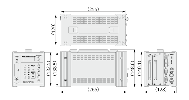
Dimensions
|
120 W x 132.5 H x 255 D mm (Excluding protrusions)
|
Weight
|
Approx.1.8 kg (Approx.2.0 kg with 2 CDV-40B cards installed.)
|
Standard Accessories
|
DC power cable P-76
USB cable N-38
Ground wire P-72
CF card (1 GB) inserted in the slot
Fuses (5 A for 2-slot model)
Dummy panel: 1pc
Installed on the free slots before shipment
EDX accessory bag
Dynamic data acquisition software DCS-100A (DVD)
*DCS-100A is optional for models with suffix -0.
Instruction manual (In English & Japanese, in the above DVD)
|
Optional Accessories
|
AC adapter UNI345-1238-AC
Fixing adapter
EDX dummy panel EDX1P-DUMMY
Remote control unit RCU-42A
Battery unit for instantaneous power failure EDB-41B
Monitor unit EMON-20A
Synchronous cable N-128
|
Specifications
Models
|
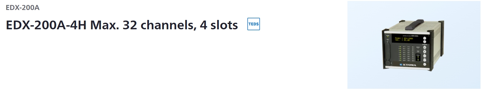
EDX-200A-4H (With DCS-100A)
EDX-200A-4H-0
EDX-200A-4H-1 (With DCS-100A and DCS-101A)
|
Measuring Targets
|
Strain (Gage, transducer)
Voltage
Thermocouples
Pulse (F/V)
Piezoelectric acceleration (Built-in amplifier)
CAN signals
GPS
|
Conditioner Cards for Analog Inputs
|
The conditioner cards for EDX series
[Note] The EDX-200A-4T can use only the CVM-41A,CDV-40B, CDV-40B-F and CAN-41A which performed temperature extension processing.
[Note] The EDX-200A limits the number of CFV-40A.
The number of CFV-40A is up to 2.
|
Conditioner Cards for CAN Data Inputs
|
CAN card (2 ports, max. 256 channels): CAN-41A
[Note] Can install one CAN-41A to the final slot.
|
Voice Memo Input
|
1 channel
(Input voice memo data is recorded together with the measurement data.)
Use remote control unit RCU-42A. (Optional accessory)
Use the Data Analysis Software DAS-200A (optional accessory) to play back recorded voice memos.
|
Sampling
Sampling Method
|
Simultaneously all channels
|
Sampling Mode
|
Normal: Records all channels’ data at the same sampling clock.
Dual: Enables high-speed sampling or low-speed sampling to every CH for recording.
|
Sampling Frequencies
Normal-sampling Mode
|
1-2-5 series
1 Hz to 100 kHz
1 Hz to 2 kHz When using CAN-41A
2n series
2 to 65536 Hz
2 to 2048 Hz When using CAN-41A
|
Dual-sampling Mode
|
High-speed sampling [Sf]
1-2-5 series
1 Hz to 100 kHz
1 Hz to 2 kHz when using CAN-41A
2n series
2 to 65536 Hz
2 to 2048 Hz when using CAN-41A
Low-speed sampling [Ss]
1-2-5 series
The division frequencies from
high-speed sampling, and Ss ≤ Sf/4
2n series
The division frequencies from
high-speed sampling, and Ss ≤ Sf/4
|
Channels
Normal-sampling Mode
|
Max. 32 channels, 320 k/I (I is the integer part of the set sampling frequency.)
|
Dual-sampling Mode
|
Max. 64 channels, 320 k/I (I is the integer part of the set sampling frequency.). “High-speed and low-speed” setting counts as 2 channels.
|
When Using CAN-41A
|
Channels of CAN data
|
The Number of Sampling Frequency
Normal Mode
|
“320000/ The number of channels” or less
|
Dual Mode
|
High-speed sampling frequency:
“320000/ The number of channels” or less.
*About high-speed and low-speed setting channels, the number of channels per channel is 2.
|
Digital Filter
|
Butterworth filter (IIR)
Type of filter: LPF, HPF
Order of a filter: 1 to 8
Amplitude ratio at cutoff point: -3 dB
Attenuation: -6 x N dB/oct. (N is order of the filter)
*Simultaneously use with built-in LPF possible.
*Application on CAN data not possible.
|
Data Recording Unit
|
CF card
Capacity: 128 MB to 16 GB (our recommended only)
Maximum data file size (available data file size to be recorded)
When the number of repeat times is 1: 4 GB/data file
When the number of repeat times is 2: 1 GB/data file
(1GB = 1000000000 bytes)
|
Control Switch
|
UP/DOWN : Changes the display on the small indicator.
REC/PAUSE : Starts and pauses data recording.
STOP : Stops data recording.
BAL. : Execute the balance.
LOAD : Loads and sets conditions.
OPT. : Conducts the pre-set arbitrary function.
ID : Sets the EDX-200A identification No.
POWER : POWER switch
USB/LAN : Selects a communication interface (USB /LAN)
[NOTE] The EDX-200A-1 does not have the UP/DOWN switch and ID switch.
|
Indicator
|
Channel status display LED:32
Unit status display LED:7
Unit status display organic EL monitor:1
|
Operating Switch
|
UP, DOWN: Status display organic EL monitor display switching
REC/PAUSE: Start/pause data recording.
STOP: Stop data recording.
BAL.: Implement balance (Balance adjustment)
LOAD: Read and configure conditions from CF card
OPT.: Execute arbitrary configured functions
ID: EDX identifier configuration
POWER: Power switch
USB/LAN: Communications I/F, switchable
|
External Control Connector
|
CONT IN, CONT OUT
(Remote control, for synchronous operation)
|
Communication interfaces
|
USB(USB2.0 High Speed) 1 port
Connector: Series B receptacle connector
LAN(10/100BASE-T) 2 ports
LAN IN connector: For PC communication
LAN OUT connector For synchronous operation
Connector: RJ45 modular jack connector
[NOTE] The EDX-200A-1 does not have the LAN OUT connector for the synchronous operation.
|
Synchronous Operation
|
Max. 8 EDX-200A units can be connected for synchronous operation by using synchronous cables N-95 N-128.
Max. 8 EDX-200A units can be connected for synchronous operation by using LAN cables.
[NOTE] The synchronous operation is not available with the EDX-200A-1.
|
How To Setting Conditions
|
Online setting: Set measuring conditions on the PC via the LAN or USB
interface.
Offline setting: Set measuring conditions by allowing the EDX-200A to
read measuring conditions in the CF card. (Use DCS-100A to set measuring conditions.)
|
Saving Conditions
|
Recording of conditioner configuration conditions and measurement conditions within the EDX built-in nonvolatile memory.
Immediate start of data collection using the previously configured measurement conditions after power-on is possible.
|
Measuring Modes
|
Manual measurement
Trigger measurement
Interval measurement
|
Manual Measurement
|
Data recording is manually started or stopped when data is recorded to a preset number of measured data.
Manual mode allows recording of voice memo during data recording.
|
Trigger Measurement
|
Data recording is automatically started when the preset trigger condition is satisfied.
*No CAN data of CAN-41A is used as the trigger condition.
|
Interval Measurement
|
Automatically recording functions based upon previously-set interval conditions
Combination with measured mode when in dual sampling
(High-speed sampling channel – Low-speed sampling channel)
Manual——————————–Manual
Trigger——————————–Manual, interval
Interval —————————— Interval
|
Starting and Stopping Data Recording
|
Data recording starts/stops by using the PC,panel switches or the RCU-42A
|
Balance Operation
|
Adjust the balance of the strain input channel and conduct the zero suppress of the voltage input CH of the CVM-41A by using the PC, control switches (on the front panel) or the RCU-42A
|
Recording Data Format
|
Kyowa standard file format KS2
Analysis using optional Data Analysis Software DAS-200A is possible.
|
Data Collection
|
Online using PC, or offline direct reading from CF card to PC
|
TEDS Function
|
TEDS function is available only when online control from the PC.
TEDS compatible conditioner cards: CDV-40B (-F),DPM-42B (-F), DPM-42B-I (-F), CCA-40A (-F),CDV-44AS, CDA-44AS, CDA-45AS, CVM-41A
|
Power Supply
|
10 to 36 VDC
Connector type: RM12BRD-4PH (Hirose)
Use DC power supply or AC adapter (Optional accessory)
|
Current Consumption
|
Approx. 2.6 A(12 VDC with 4 CDV-40B card installed)
|
Operating Temperature
|
0 to 50ºC
|
Operating Humidity
|
20 to 90% (Non-condensing)
|
Storage Temperature
|
−20 to 60ºC
|
Vibration Resistant
|
49.0 m/s2 (5 G), 5 to 55 Hz 1 cycle 1 min., each axis 15 cycles
(Non-operating)29.4 m/s2 (3 G), 5 to 55 Hz 1 cycle 1 min., each axis 15cycles
(Operating)
|
Impact Resistant
|
196.1 m/s2 (20 G) /11 ms
|
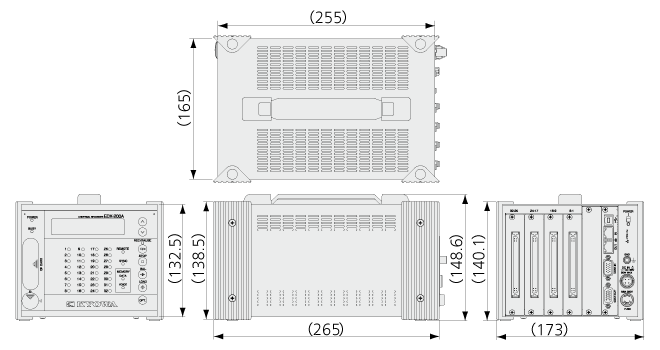
Dimensions
|
165 W x 132.5 H x 255 D mm (Excluding protrusions)
|
Weight
|
Approx. 2.1kg (2.6 kg with 4 CDV-40B cards installed.)
|
Standard Accessories
|
DC power cable P-76
USB cable N-38
Ground wire P-72
CF card (1 GB) inserted in the slot
Fuses (8 A for 4-slot model)
Dummy panel: 3 pc
Installed on the free slots before shipment
EDX accessory bag
Dynamic data acquisition software DCS-100A (DVD)
*DCS-100A is optional for models with suffix -0.
Instruction manual (In English & Japanese, in the above DVD)
|
Optional Accessories
|
AC adapter UNI360-1540-AC
Fixing adapter
EDX dummy panel EDX1P-DUMMY
Remote control unit RCU-42A
Battery unit for instantaneous power failure EDB-41B
Monitor unit EMON-20A
Synchronous cable N-128
|
Specifications
Models
|
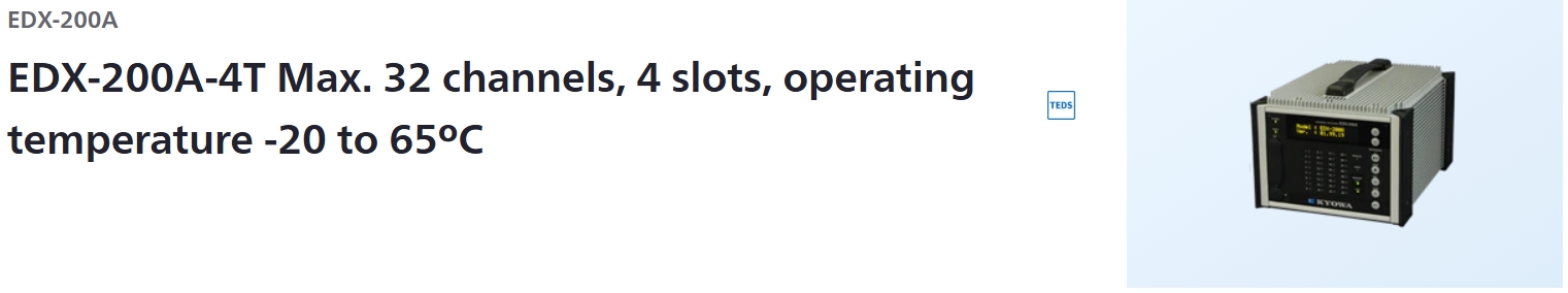
EDX-200A-4T (With DCS-100A)
EDX-200A-4T-0
EDX-200A-4T-1 (With DCS-100A and DCS-101A)
|
Measuring Targets
|
Strain (Gage, transducer)
Voltage
Thermocouples
Pulse (F/V)
Piezoelectric acceleration (Built-in amplifier)
CAN signals
GPS
|
Conditioner Cards for Analog Inputs
|
The conditioner cards for EDX series
[Note] The EDX-200A-4T can use only the CVM-41A,CDV-40B, CDV-40B-F and CAN-41A which performed temperature extension processing.
[Note] The EDX-200A limits the number of CFV-40A.
The number of CFV-40A is up to 2.
|
Conditioner Cards for CAN Data Inputs
|
CAN card (2 ports, max. 256 channels): CAN-41A
[Note] Can install one CAN-41A to the final slot.
|
Voice Memo Input
|
1 channel
(Input voice memo data is recorded together with the measurement data.)
Use remote control unit RCU-42A. (Optional accessory)
Use the Data Analysis Software DAS-200A (optional accessory) to play back recorded voice memos. |
Sampling
Sampling Method
|
Simultaneously all channels
|
Sampling Mode
|
Normal: Records all channels’ data at the same sampling clock.
Dual: Enables high-speed sampling or low-speed sampling to every CH for recording.
|
Sampling Frequencies
Normal-sampling Mode
|
1-2-5 series
1 Hz to 100 kHz
1 Hz to 2 kHz When using CAN-41A
2n series
2 to 65536 Hz
2 to 2048 Hz When using CAN-41A |
Dual-sampling Mode
|
High-speed sampling [Sf]
1-2-5 series
1 Hz to 100 kHz
1 Hz to 2 kHz when using CAN-41A
2n series
2 to 65536 Hz
2 to 2048 Hz when using CAN-41A
Low-speed sampling [Ss]
1-2-5 series
The division frequencies from
high-speed sampling, and Ss ≤ Sf/4
2n series
The division frequencies from
high-speed sampling, and Ss ≤ Sf/4
|
Channels
Normal-sampling Mode
|
Max. 32 channels, 320 k/I (I is the integer part of the set sampling frequency.)
|
Dual-sampling Mode
|
Max. 64 channels, 320 k/I (I is the integer part of the set sampling frequency.). “High-speed and low-speed” setting counts as 2 channels.
|
When Using CAN-41A
|
Channels of CAN data
|
The Number of Sampling Frequency
Normal Mode
|
“320000/ The number of channels” or less
|
Dual Mode
|
High-speed sampling frequency:
“320000/ The number of channels” or less.
*About high-speed and low-speed setting channels, the number of channels per channel is 2.
|
Digital Filter
|
Butterworth filter (IIR)
Type of filter: LPF, HPF
Order of a filter: 1 to 8
Amplitude ratio at cutoff point: -3 dB
Attenuation: -6 x N dB/oct. (N is order of the filter)
*Simultaneously use with built-in LPF possible.
*Application on CAN data not possible.
|
Data Recording Unit
|
CF card
Capacity: 128 MB to 16 GB (our recommended only)
Maximum data file size (available data file size to be recorded)
When the number of repeat times is 1: 4 GB/data file
When the number of repeat times is 2: 1 GB/data file
(1GB = 1000000000 bytes)
|
Control Switch
|
UP/DOWN : Changes the display on the small indicator.
REC/PAUSE : Starts and pauses data recording.
STOP : Stops data recording.
BAL. : Execute the balance.
LOAD : Loads and sets conditions.
OPT. : Conducts the pre-set arbitrary function.
ID : Sets the EDX-200A identification No.
POWER : POWER switch
USB/LAN : Selects a communication interface (USB /LAN)
[NOTE] The EDX-200A-1 does not have the UP/DOWN switch and ID switch.
|
Indicator
|
Channel status display LED:32
Unit status display LED:7
Unit status display organic EL monitor:1
|
Operating Switch
|
UP, DOWN: Status display organic EL monitor display switching
REC/PAUSE: Start/pause data recording.
STOP: Stop data recording.
BAL.: Implement balance (Balance adjustment)
LOAD: Read and configure conditions from CF card
OPT.: Execute arbitrary configured functions
ID: EDX identifier configuration
POWER: Power switch
USB/LAN: Communications I/F, switchable
|
External Control Connector
|
CONT IN, CONT OUT
(Remote control, for synchronous operation)
|
Communication interfaces
|
USB(USB2.0 High Speed) 1 port
Connector: Series B receptacle connector
LAN(10/100BASE-T) 2 ports
LAN IN connector: For PC communication
LAN OUT connector For synchronous operation
Connector: RJ45 modular jack connector
|
Synchronous Operation
|
Max. 8 EDX-200A units can be connected for synchronous operation by using synchronous cables N-95 N-128.
Max. 8 EDX-200A units can be connected for synchronous operation by using LAN cables.
[NOTE] The synchronous operation is not available with the EDX-200A-1.
|
How To Setting Conditions
|
Online setting: Set measuring conditions on the PC via the LAN or USB
interface.
Offline setting: Set measuring conditions by allowing the EDX-200A to
read measuring conditions in the CF card. (Use DCS-100A to set measuring conditions.)
|
Saving Conditions
|
Recording of conditioner configuration conditions and measurement conditions within the EDX built- in nonvolatile memory.
Immediate start of data collection using the previously configured measurement conditions after power-on is possible.
|
Measuring Modes
|
Manual measurement
Trigger measurement
Interval measurement
|
Manual Measurement
|
Data recording is manually started or stopped when data is recorded to a preset number of measured data.
Manual mode allows recording of voice memo during data recording.
|
Trigger Measurement
|
Data recording is automatically started when the preset trigger condition is satisfied.
*No CAN data of CAN-41A is used as the trigger condition.
|
Interval Measurement
|
Automatically recording functions based upon previously-set interval conditions
Combination with measured mode when in dual sampling
(High-speed sampling channel – Low-speed sampling channel)
Manual——————————–Manual
Trigger——————————–Manual, interval
Interval —————————— Interval
|
Starting and Stopping Data Recording
|
Data recording starts/stops by using the PC,panel switches or the RCU-42A
|
Balance Operation
|
Adjust the balance of the strain input channel and conduct the zero suppress of the voltage input CH of the CVM-41A by using the PC, control switches (on the front panel) or the RCU-42A
|
Recording Data Format
|
Kyowa standard file format KS2
Analysis using optional Data Analysis Software DAS-200A is possible.
|
Data Collection
|
Online using PC, or offline direct reading from CF card to PC
|
TEDS Function
|
TEDS function is available only when online control from the PC.
TEDS compatible conditioner cards: CDV-40B (-F),DPM-42B (-F), DPM-42B-I (-F), CCA-40A (-F),CDV-44AS, CDA-44AS, CDA-45AS, CVM-41A
|
Power Supply
|
10 to 36 VDC
Connector type: RM12BRD-4PH (Hirose)
Use DC power supply or AC adapter (Optional accessory)
|
Current Consumption
|
Approx. 2.6 A (12 VDC with 4 CDV-40B card installed)
|
Operating Temperature
|
-20 to 65ºC
|
Operating Humidity
|
20 to 90% (Non-condensing)
|
Storage Temperature
|
−30 to 70ºC
|
Vibration Resistant
|
49.0 m/s2 (5 G), 5 to 55 Hz 1 cycle 1 min., each axis 15 cycles
(Non-operating)
29.4 m/s2 (3 G), 5 to 55 Hz 1 cycle 1 min., each axis 15cycles
(Operating)
|
Impact Resistant
|
196.1 m/s2 (20 G) /11 ms
|
Dimensions
|
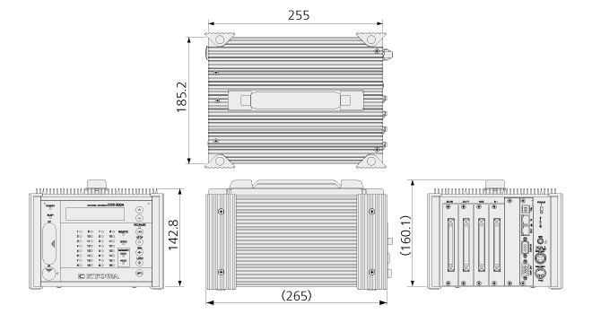
185.2 W x 142.8 H x 255 D mm (Excluding protrusions)
|
Weight
|
Approx. 3.7 kg (Approx.4.2 kg with 4 CDV-40B cards installed.)
|
Standard Accessories
|
DC power cable P-76
USB cable N-38
Ground wire P-72
CF card (1 GB) inserted in the slot
Fuses (8 A for 4-slot model)
EDX accessory bag
Dynamic data acquisition software DCS-100A (DVD)
*DCS-100A is optional for models with suffix -0.
Instruction manual (In English & Japanese, in the above DVD)
|
Optional Accessories
|
AC adapter UNI360-1540-AC
Fixing adapter
EDX dummy panel EDX1P-DUMMY
Remote control unit RCU-42A
Monitor unit EMON-20A
Synchronous cable N-128
|


 Contact Sales
  Spec Sheet