
 Contact Sales
  Spec Sheet
 Description
Features
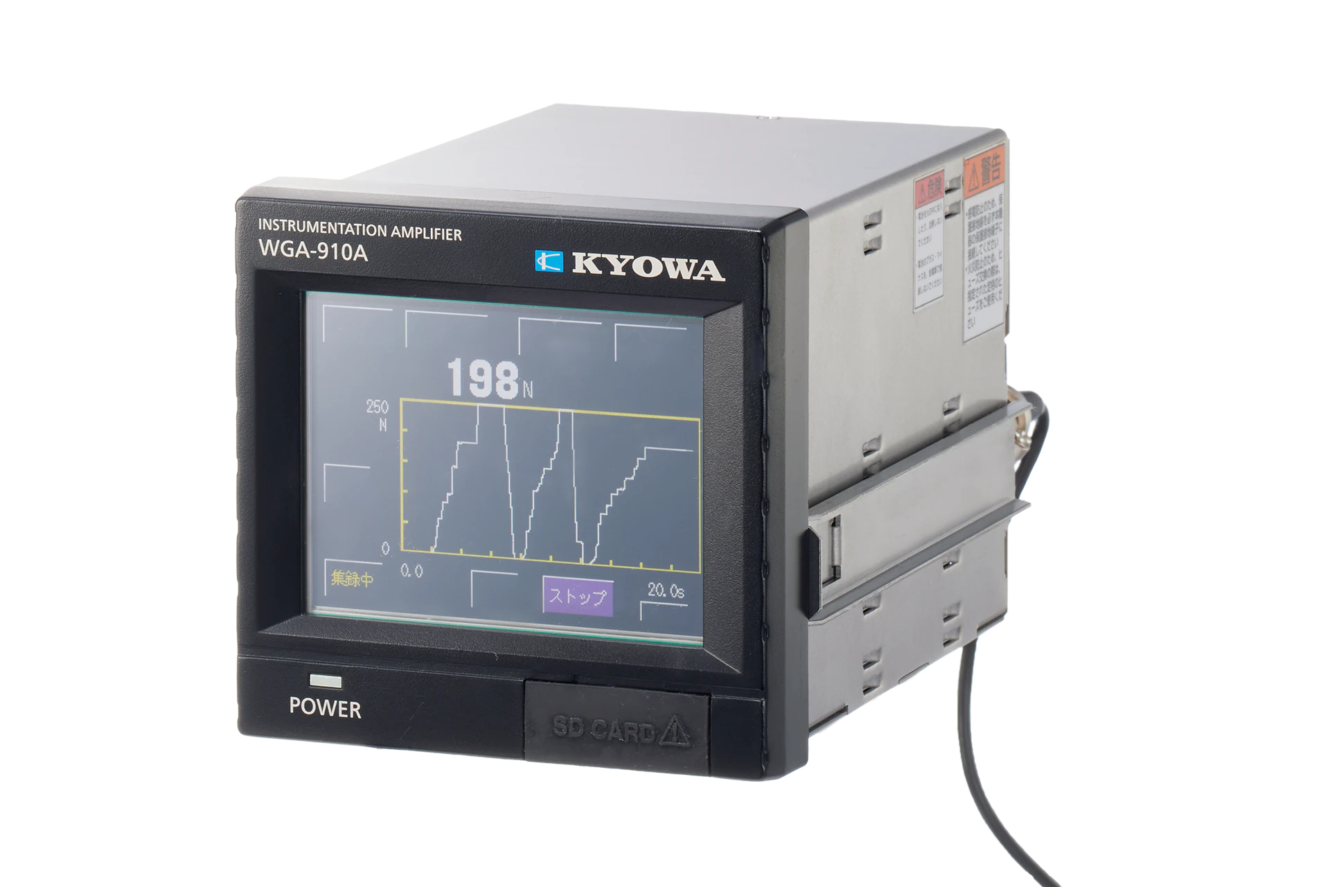
- Monitor waveforms and check numbers easily using the touch panel
- Variety of hold functions
- Waveform comparison function
- SD card compatible

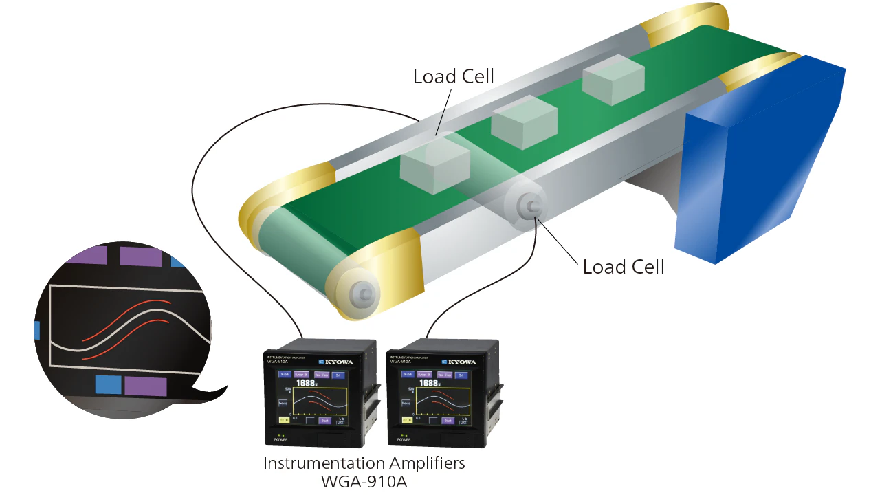
Load Management by Comparing Waveforms
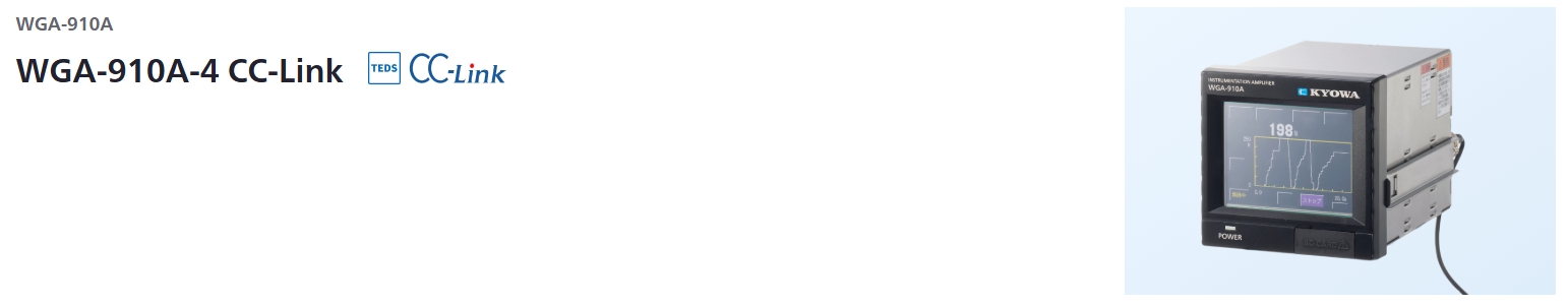
WGA-910A can be used to display waveforms and numerical data for loads on manufacturing lines, measured by load cells. Advanced load management can also be performed by comparing upper/lower limit set waveforms with actual measured waveforms.
Specifications
Standard Specifications
Channels |
1 |
|---|---|
Applicable Transducers |
Strain-gage transducers
|
Compatible Bridge Resistance |
87.5 Ω to 1 kΩ
|
TEDS Compatible |
Interface:
|
Bridge Excitation |
10, 2 VDC, selectable |
Measuring Range |
-3.2 to 3.2 mV/V
|
Zero Adjustment Range |
Within measurement range
|
Nonlinearity |
Within ±(0.02% FS + 1 digit) |
Stability |
Zero point: Within ±0.25μVRTI per°C
|
Peak/Bottom Detection |
Detecting scheme: Digital hold |
Frequency Response |
DC to 1 kHz (+1 dB, -2 dB) |
Sampling Speed |
4000 times/s |
AD Resolution |
24 bits |
Analog Monitor |
Voltage output: ±(5 V ±200 mV)
|
Indicators |
3.5-inch TFT color LCD
|
Indication |
Setting range: -99999 to 99999
|
Calibration Function |
Manual calibration:
|
Smoothing Functions |
Analog filter (LPF): 1, 30, 300 Hz, Flat (1 kHz or more)
|
Zero Compensation Function |
Zero tracking (Auto digital Zero within the setting range)
|
Additional Value |
-99999 to 99999 count |
Original Values (Sensor Output Value) |
-3.2000 to 3.2000 mV/V (5 digits)
|
Measurement Condition Numbers |
32 (16 for control input) of measurement condition file can be saved.
|
Comparator Setting |
Points: 4Types: Extra high (HH), high (HI), low (LO), extra low (LL) If there are 2 hold values, they are assigned as follows. Setting range: ±99999 Hysteresis width: 0 to 9999 Output logic: Positive/negative Comparison speed: 4000 times/s (Normal comparative mode) |
Judgment Function |
Point : 1
|
Waveform Comparison Setting |
Points: 2
|
Waveform Judgment Function |
Type : 1
|
Motion Detect |
Motion detect function: Enable/disable
|
Measuring Mode Setting |
Operation modes:
|
Waveform Display |
X-axis setting
|
System |
Key lock
|
Self-check |
Memory
|
Operation Check |
Display
|
Control Input |
Points: 9Types: Zero command, hold command, reset command, waveform command, TEDS command, measurement condition select 0 to 3 Signal formats: Open collector (NPN) or non-voltage contact signal |
Control Output |
Points: 16Types: HH, HI, OK, LO, LL, healthy, abnormal channel, abnormal memory, SD, communication error Output type: Open collector (NPN) Load capacity: 30 VDC, 20 mA (Load resistance) |
Communication |
Signal system: RS-232C, full duplex systemTransmission system: Asynchronous Bit configuration Transmission mode: Repeat output, output at hold, Tx and Rx NOTE: When equipping the optional CC-Link (RS-485), the RS-232C of the standard equipment is disabled. Otherwise, RS-232C is enabled. |
SD Card |
Saving setting value:
|
Power Supply |
100 to 240 V, power consumption: 20 VA or less |
Dimensions |
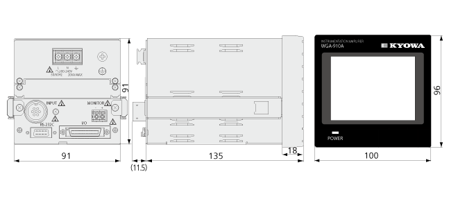
100 W ×96 H ×135 D mm (Excluding protrutions) |
Weight |
Approx. 950 g (Excluding options) |
Operating Temperature |
-10 to 40 °C |
Operating Humidity |
20 to 85% or less (Non-condensing) |
Compliance |
Directive 2014/30/EU (EMC)
|
Standard Accessories |
CD (Instruction manual, PC software for SD card) |
|---|---|
Optional Accessories |
AC power cable P-23 (For 100 VAC)
|
Dimensions
Optional Specifications
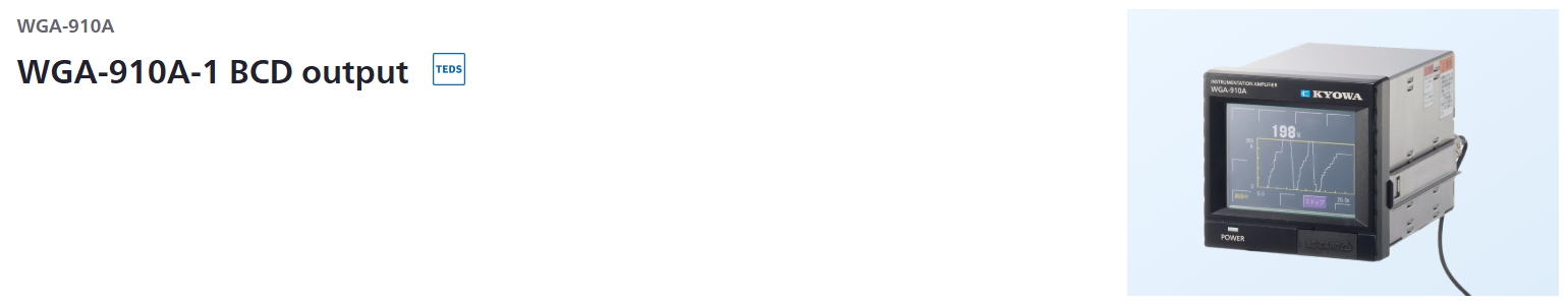
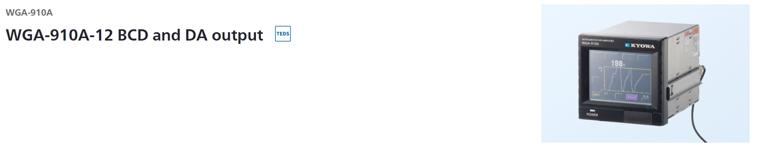
BCD Output
Output |
BCD data: 20 bits (4 bits × 5 digits)
|
|---|---|
Input |
Points: 2Details: Input signal type: |
Setting Content |
Transmission speed:
|
Optional Specifications
BCD/Binary Output
Output |
BCD data: 20 bits (4 bits × 5 digits)
|
|---|---|
Input |
Points: 2Details: Input signal type: |
Setting Content |
Transmission speed: Approx. 16, 32, 64, 125, 250, 500, 1000 times/s
|
DA Output
Output Voltage |
±10 V (load resistance 2 kΩ or more)
|
|---|---|
Output Current |
4 to 20 mA (load resistance 500 Ω or less)
|
Insulation Voltage |
250 VAC for 1 minute
|
Conversion Speed |
2000 times/s |
Nonlinearity |
0.1% FS |
Setting Content |
DA display:
|
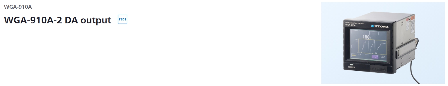
Optional Specifications
DA Output
Output Voltage |
±10 V (load resistance 2 kΩ or more)
|
|---|---|
Output Current |
4 to 20 mA (load resistance 500 Ω or less)
|
Insulation Voltage |
250 VAC for 1 minute
|
Conversion Speed |
4000 times/s |
Nonlinearity |
±0.1% FS |
Setting Content |
DA display:
|
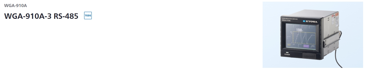
Optional Specifications
RS-485
Signaling System |
RS-485 half duplex system |
|---|---|
Bit Configuration |
Data bits: 7
|
Flow Control |
None |
Setting Content |
Device ID: 1 to 99
|
Optional Specifications
CC-Link
Version |
Ver.1.10 |
|---|---|
Station Type |
Remote device station |
Occupied Stations |
1 station
|
Communication Speed |
10 Mbps
|
Device Stations |
1 to 64 |
Connection Cable |
CC-Link Ver.1.10-compliant cable
|
Optional Accessories |
Wire mount socket 35505-6000-BOM GF
|
|---|