


 Contact Sales
  Spec Sheet
 Description
Features
- Wireless strain/temperature measurement up to approx. 50 m
- Can also measure objects in motion*1
- Certified under radio laws in Japan, US, China, Thailand, Taiwan, EU, and India*1
- Max. continuous usage time: 34 hours*2
- Compatible with 1-gage 2/3-wire, 4-gage*3
*1 Varies by model
*2 Two AAA LR03EJ used for a 1-channel strain transmitter
*3 Separate bridge adapter and input adapter required
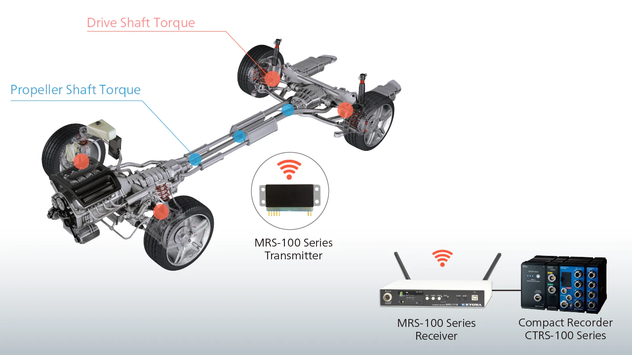
Drivetrain Performance Testing
MRS-100 Series devices are wireless, so they can be used to measure torque, vibration, stress, and temperature of rotating parts around drivetrains, such as torque converters, flywheels, and drive shafts. MRS-100 Series devices operate at a high sampling rate, so that test data can be transmitted nearly in real-time—even when measuring high-speed phenomena.
Contents
■Transmitters
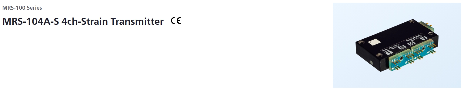
MRS-104A-S: 4 channels, for strain, built-in antenna
Radio law certification Japan, the USA, China, India, Thailand, Taiwan, EU
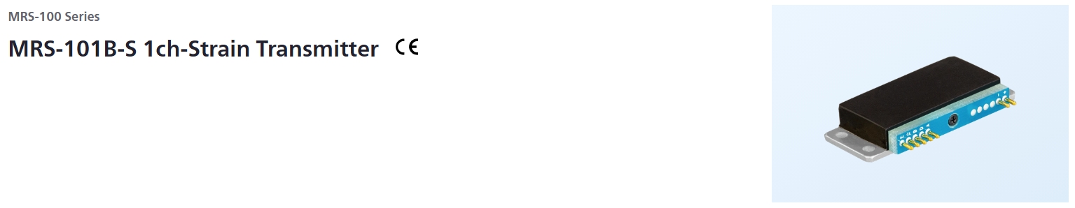
MRS-101B-S: 1 channel, for strain, built-in antenna
Radio law certification Japan, the USA, China, India, Thailand, Taiwan, EU
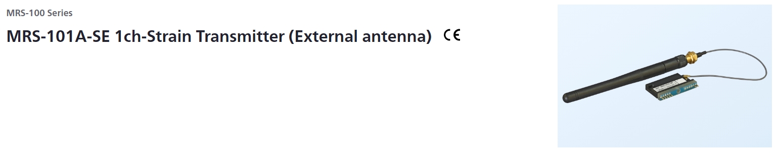
MRS-101A-SE: 1 channel, for strain, external antenna
Radio law certification Japan, the USA, India, EU, Thailand
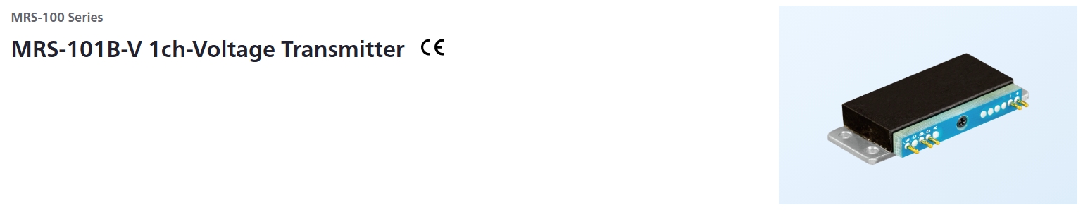
MRS-101B-V: 1 channel, for voltage, built-in antenna
Radio law certification Japan, the USA, China, India, Thailand, Taiwan, EU
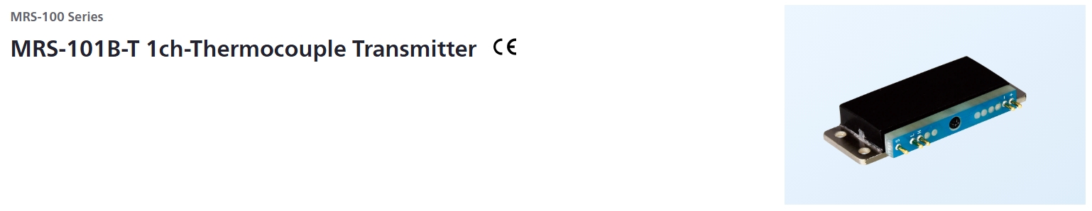
MRS-101B-T: 1 channel, for thermocouple, built-in antenna
Radio law certification Japan, the USA, China, India, Thailand, Taiwan, EU
■Receivers
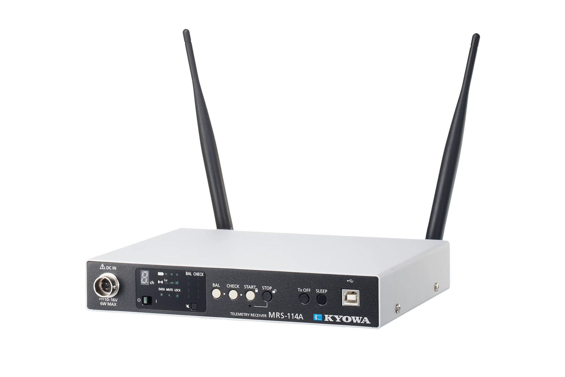
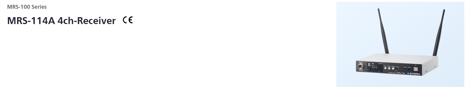
MRS-114A: 4 channels
Radio law certification Japan, the USA, China, India, Thailand, Taiwan, EU
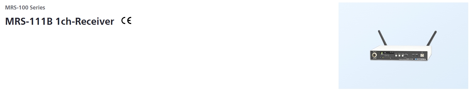
MRS-111B: 1 channel
Radio law certification Japan, the USA, China, India, Thailand, Taiwan, EU
Remarks
*Korean compatible models are available. Inquiries are welcome.
Specifications
Hardware Specifications
Measuring Targets |
Strain gages (Full bridge system*)
|
|---|---|
Channels |
Max. 4 |
Compatible Bridge Resistance |
120 to 1000 Ω |
Gage Factor |
2.00 fixed |
Bridge Excitation |
1 VDC |
Measuring Range |
1000, 2500, 5000, 10000, 25000 ×10-6 strain |
Measuring Accuracy |
Within ±0.15% FS
|
Balance Adjustment Range |
Within ±10000 ×10-6 strain |
AD Resolution |
16 bits |
Sampling Frequencies |
1 channel: 4.8 kHz
|
Temperature Stability |
Zero point: Within ±0.05 ×10⁻⁶ strain per °C
|
Operating Temperature |
-25 to 75°C*If the ambient temperature exceeds 50°C, it cannot be used in a vibration, shock, centrifugal acceleration by fixing the bolts in the body mounting holes. |
Operating Humidity |
20 to 85% (Non-condensing) |
Vibration Resistance |
294.2 m/s2 (30 G), 10 to 500 Hz*If the ambient temperature exceeds 50°C, it cannot be used in a vibration, shock, centrifugal acceleration by fixing the bolts in the body mounting holes. |
Shock Resistance |
980.7 m/s2 (100 G), 11 ms or less, half sine wave*If the ambient temperature exceeds 50°C, it cannot be used in a vibration, shock, centrifugal acceleration by fixing the bolts in the body mounting holes. |
Centrifugal Acceleration Resistance |
980.7 m/s2 (100 G)*If the ambient temperature exceeds 50°C, it cannot be used in a vibration, shock, centrifugal acceleration by fixing the bolts in the body mounting holes. |
Power Supply |
2.2 to 4.4 VDC |
Current Consumption |
Within 62 mA
|
Hours of Continuous Use |
Approx. 12 h [Lithium (CR2 manufactured by Panasonic)]
|
Dimensions |
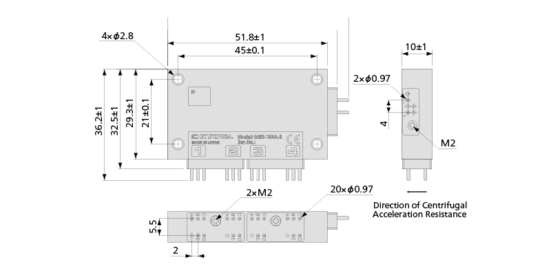
55 W × 10 H × 32.5 D mm (Excluding protrusions, with adapter) |
Weight |
Approx. 32 g (With adapter) |
Compliance |
Directive 2014/53/EU (RED)
|
RF Specifications
Transceiver Frequency Channel |
1 (Choose 1 channel from 16 channels using Setting software) |
|---|---|
Antennas |
Built-in |
Radio Communication Frequency Band |
2.4 GHz band |
Radio System |
Digital modulation system |
Radio Certification |
Japan, the USA, China, India, Thailand, Taiwan, EU |
Communication Distance |
50 m (Max. line of sight distance) |
Environment of Usage |
Environment where the wireless LAN and the Bluetooth🄬, etc. are not intermingled on the 2.4 GHz. |
Frequency Channel and Central Frequency |
Frequency channel————–Central frequency (GHz)
|
Combination Specifications of Transmitter with Receiver
Compatible Receiver |
MRS-114A firmware ver. 3.00 or later*No MRS-104A-S be used in combination with a 1-channel receiver. |
|---|---|
Analog Output Voltage |
±5 V/Full scale range |
Combination Measuring Accuracy |
Within ±0.2% FS |
Frequency Response |
Measuring channel: 1
|
Delay Time |
Measuring channel: 1
|
Standard Accessories |
Full-bridge adapter ADP-401 × 2
|
|---|---|
Optional Accessories |
Quarter-bridge 2-wire adapter (120 Ω) ADP-402-120 (2 channels/pc)
|
Dimensions
Specifications
Hardware Specifications
Measuring Targets |
Strain gages (Full bridge system*)
|
|---|---|
Channels |
1 |
Compatible Bridge Resistance |
120 to 1000 Ω |
Gage Factor |
2.00 fixed |
Bridge Excitation |
1 VDC |
Measuring Range |
1000, 2500, 5000, 10000, 25000 ×10-6 strain |
Range Accuracy |
Within ±0.15% FS
|
Balance Adjustment Range |
Within ±10000 ×10-6 strain |
AD Resolution |
16 bits |
Sampling Frequencies |
4.8 kHz |
Temperature Stability |
Zero point: Within ±0.05 ×10⁻⁶ strain per °C
|
Operating Temperature |
-25 to 75°C |
Operating Humidity |
20 to 85% (Non-condensing) |
Vibration Resistance |
294.2 m/s2 (30 G), 10 to 500 Hz |
Shock Resistance |
980.7 m/s2 (100 G), 11 ms or less, half sine wave |
Centrifugal Acceleration Resistance |
29420 m/s2 (3000 G) *1, *2*1 The figures are when installed with our specified screws and torque. |
Power Supply |
2.2 to 4.4 VDC |
Current Consumption |
Within 32 mA
|
Hours of Continuous Use |
Approx. 28 h [Lithium (CR2 manufactured by Panasonic)]
|
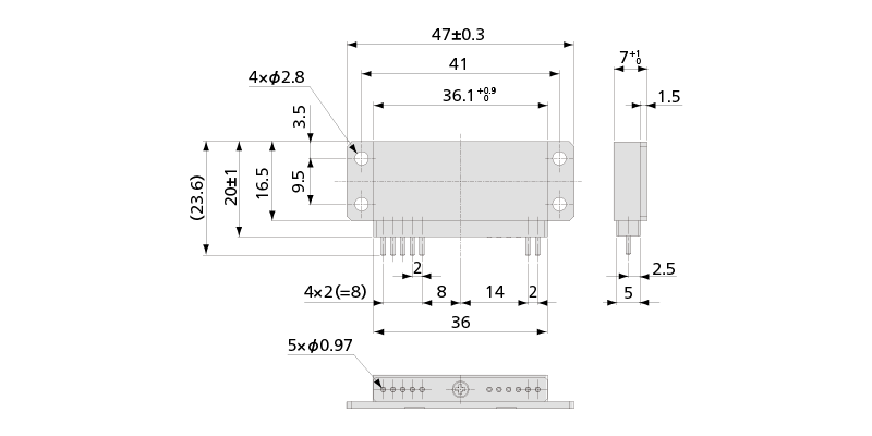
Dimensions |
47 W × 7 H × 20 D mm
|
Weight |
Approx. 17 g (With adapter) |
Compliance |
Directive 2014/53/EU (RED)
|
RF Specifications
Transceiver Frequency Channel |
1 (Choose 1 channel from 16 channels using Setting software) |
|---|---|
Antennas |
Built-in |
Radio Communication Frequency Band |
2.4 GHz band |
Radio System |
Digital modulation system |
Radio Certification |
Japan, the USA, China, India, Thailand, Taiwan, EU |
Communication Distance |
50 m (Max. line of sight distance) |
Environment of Usage |
Environment where the wireless LAN and the Bluetooth🄬, etc. are not intermingled on the 2.4 GHz. |
Frequency Channel and Central Frequency |
Frequency channel————–Central frequency (GHz)
|
Combination Specifications of Transmitter with Receiver
Compatible Receiver |
MRS-114A Firmware Ver. 3.01 or later
|
|---|---|
Analog Output Voltage |
±5 V/Full scale range |
Combination Measuring Accuracy |
Within ±0.2% FS |
Frequency Response |
DC to 370 Hz (Deviation +0.5, -1 dB)
|
Delay Time |
11.1 ±0.3 ms (at DC to 480 Hz)Only 1 transmitter can be used in combination with 1 receiver. |
Standard Accessories |
Full-bridge adapter ADP-11S
|
|---|---|
Optional Accessories |
MRS junction kit MRS-J11B
|
Dimensions
Hardware Specifications
Measuring Targets |
Strain gages (Full bridge system*)
|
|---|---|
Channels |
1 |
Compatible Bridge Resistance |
120 to 1000 Ω |
Gage Factor |
2.00 fixed |
Bridge Excitation |
1 VDC |
Measuring Range |
1000, 2500, 5000, 10000, 25000 ×10-6 strain |
Range Accuracy |
Within ±0.15% FS |
Balance Adjustment Range |
Within ±10000 ×10-6 strain |
AD Resolution |
16 bits |
Sampling Frequencies |
4.8k Hz |
Temperature Stability |
Zero point: Within ±0.05×10⁻⁶ strain per °C
|
Operating Temperature |
-25 to 75°C *1 |
Operating Humidity |
20 to 85% (Non-condensing) |
Vibration Resistance |
29.42 m/s2 (3 G), 5 to 200 Hz *1 |
Shock Resistance |
294.2 m/s2 (30 G), 11 ms or less, half sine wave *1 |
Power Supply |
2.2 to 4.4 VDC |
Current Consumption |
Within 32 mA
|
Hours of Continuous Use |
Approx.28 h [Lithium (CR2 manufactured by Panasonic)]
|
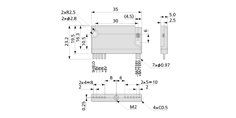
Dimensions |
35 W × 5.0 H ×19.5 D mm (Excluding protrusions) |
Weight |
Approx. 10 g |
*1 If the ambient temperature exceeds 50℃, it cannot be used in a vibration, shock, centrifugal acceleration by fixing the bolts in the body mounting holes. |
RF Specifications
Transceiver Frequency Channel |
1 (Choose 1 channel from 16 channels using Setting software) |
|---|---|
Antennas |
Specified external
|
Radio Communication Frequency Band |
2.4G Hz band |
Radio System |
Digital modulation system |
Radio Certification |
Japan, the USA, India, EU, Thailand |
Communication Distance |
50 m (Max. line of sight distance)
|
Environment of Usage |
Environment where the wireless LAN and the Bluetooth🄬, etc. are not intermingled on the 2.4 GHz. |
Frequency Channel and Central Frequency |
Frequency channel————–Central frequency (GHz)
|
Combination Specifications of Transmitter with Receiver
Analog Output Voltage |
±5 V/Full scale range |
|---|---|
Accuracy |
Within ±0.2% FS |
Frequency Response |
Measuring channel: 1
|
Delay Time |
11.1 ±0.3 ms (at DC to 480 Hz)Only 1 transmitter can be used in combination with 1 receiver. |
Standard Accessories |
Adapter board ADP-01
|
|---|---|
Optional Accessories |
Quarter-bridge 2-wire adapter (120 Ω) ADP-02-120
|
Dimensions
Specifications
Hardware Specifications
Measuring Targets |
Thermocouples |
|---|---|
Channels |
1 |
Compatible Thermocouples |
K, T, N, J
|
Measuring Range |
K1300: -200 to 1300ºC
|
Range Accuracy |
Ambient temperature: 20 to 30ºC
|
Check Function |
Burnout check |
AD Resolution |
16 bits |
Sampling Frequencies |
50 Hz |
Operating Temperature |
-25 to 75 ºC |
Operating Humidity |
20 to 85 % (Non-condensing) |
Vibration Resistance |
294.2 m/s2 (30 G),10 to 500 Hz |
Shock Resistance |
980.7 m/s2 (100 G),11 ms or less, half sine wave |
Centrifugal Acceleration Resistance |
29420 m/s2 (3000 G)
|
Power Supply |
2.2 to 4.4 VDC |
Current Consumption |
Within 24 mA (Test conditions: Power supply 3.0 V) |
Hours of Continuous Use |
Approx. 33 h [Lithium (CR2 manufactured by Panasonic)]
|
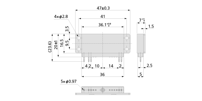
Dimensions |
47 W × 7 H × 20 D mm (Excluding protrusions, with adapter) |
Weight |
Approx. 17 g (With adapter) |
Compliance |
Directive 2014/53/EU (RED)
|
RF Specifications
Transceiver Frequency Channel |
1 (Choose 1 channel from 16 channels using Setting software) |
|---|---|
Antennas |
Built-in |
Radio Communication Frequency Band |
2.4 GHz band |
Radio System |
Digital modulation system |
Radio Certification |
Japan, the USA, China, India, Thailand, Taiwan, EU |
Communication Distance |
50 m (Max. line of sight distance) |
Environment of Usage |
Environment where the wireless LAN and the Bluetooth🄬, etc. are not intermingled on the 2.4 GHz. |
Frequency Channel and Central Frequency |
Frequency channel————–Central frequency (GHz)
|
Combination Specifications of Transmitter with Receiver
Compatible Receiver |
MRS-114A Firmware Ver. 3.01 or later
|
|---|---|
Analog Output Voltage |
±5 V/Full scale rangeMeasuring Range: K1300, N1300 Measuring Range: K500, N500 Measuring Range: K100, N100 Measuring Range: T400 Measuring Range: T100 Measuring Range: J1200 Measuring Range: J500 Measuring Range: J100 |
Combination Measuring Accuracy |
Ambient Temperature: 20 to 30°C
|
Frequency Response |
DC to 6 Hz (Deviation +0.5, -1 dB), -3 ±1 dB (at 10.5 Hz) |
Delay Time |
125 ±25 ms (at DC to 10.5 Hz) |
Standard Accessories |
Thermocouples adapter ADP-11T
|
|---|---|
Optional Accessories |
Thermocouples adapter ADP-11T
|
Dimensions
Specifications
Hardware Specifications
Measuring Targets |
Voltage |
|---|---|
Channels |
1 |
Input Impedance |
Approx. 1 MΩ + 1 MΩ |
Absolute Input Voltage |
Between D (+IN) and B (-IN): Within ±32 V
|
Measuring Range |
5, 10 V |
Range Accuracy |
Within ±0.15% FS
|
Balance Adjustment Range |
Within ±5 V |
AD Resolution |
16 bits |
Sampling Frequencies |
4.8 kHz |
Temperature Stability |
Zero point: Within ±0.01% FS per °C
|
Operating Temperature |
-25 to 75°C |
Operating Humidity |
20 to 85% (Non-condensing) |
Vibration Resistance |
294.2 m/s2 (30 G), 10 to 500 Hz |
Shock Resistance |
980.7 m/s2 (100 G), 11 ms or less, half sine wave |
Centrifugal Acceleration Resistance |
29420 m/s2 (3000 G)*1 The figures are when installed with our specified screws and torque. |
Power Supply |
2.2 to 4.4 VDC |
Current Consumption |
Within 22 mA (Test conditions: Power supply 3.0 V) |
Hours of Continuous Use |
Approx. 38 h [Lithium (CR2 manufactured by Panasonic)]
|
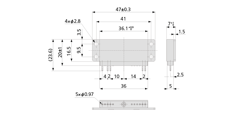
Dimensions |
47 W × 7 H × 20 D mm
|
Weight |
Approx. 17 g (With adapter) |
Compliance |
Directive 2014/53/EU (RED)
|
RF Specifications
Transceiver Frequency Channel |
1 (Choose 1 channel from 16 channels using Setting software) |
|---|---|
Antennas |
Built-in |
Radio Communication Frequency Band |
2.4 GHz band |
Radio System |
Digital modulation system |
Radio Certification |
Japan, the USA, China, India, Thailand, Taiwan, EU |
Communication Distance |
50 m (Max. line of sight distance) |
Environment of Usage |
Environment where the wireless LAN and the Bluetooth🄬, etc. are not intermingled on the 2.4 GHz. |
Frequency Channel and Central Frequency |
Frequency channel————–Central frequency (GHz)
|
Combination Specifications of Transmitter with Receiver
Compatible Receiver |
MRS-114A Firmware Ver. 3.01 or later
|
|---|---|
Analog Output Voltage |
±5 V/Full scale range |
Combination Measuring Accuracy |
Within ±0.2% FS |
Frequency Response |
DC to 370 Hz (Deviation +0.5, -1 dB)
|
Delay Time |
11.1 ±0.3 ms (at DC to 480 Hz)Only 1 transmitter can be used in combination with 1 receiver. |
Standard Accessories |
Voltage adapter ADP-11V
|
|---|---|
Optional Accessories |
MRS junction kit MRS-J11B
|
Dimensions
Specifications
Hardware Specifications
Channels |
Max. 4, 1 for combining with 1-channel transmitter.
|
|---|---|
Analog Output Voltage |
±5 V/Full scale range |
Analog Output Accuracy |
Within ±0.1% FS |
DA Resolution |
16 bits |
DA Conversion Speed |
MRS-101A-S: 4.8 kHz
|
Operating Temperature |
0 to 50°C |
Operating Humidity |
20 to 85% (Non-condensing) |
Vibration Resistance |
29.42 m/s2 (3 G), 5 to 200 Hz |
Shock Resistance |
294.2 m/s2 (30 G), 11 ms or less, half sine wave |
Power Supply |
10 to 16 VDC |
Current Consumption |
280 mA or less |
Operating Switch |
MUTE: Turn buzzer on/off.
|
Indicator |
Monitor transmitter battery in 3 steps.
|
Dimensions |
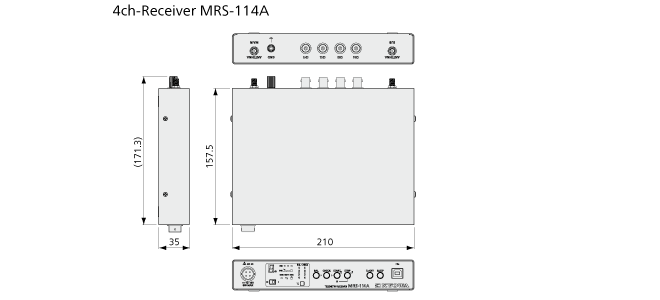
210 W × 35 H × 157.5 D mm (Excluding protrusions) |
Weight |
Approx. 600 g |
Compliance |
Directive 2014/53/EU (RED)
|
RF Specifications
Transceiver Frequency Channel |
1 (Choose 1 channel from 16 channels using Setting software) |
|---|---|
Antennas |
Specified external
|
Radio Communication Frequency Band |
2.4 GHz band |
Radio System |
Digital modulation system |
Radio Certification |
Japan, the USA, China, India, Thailand, Taiwan, EU |
Communication Distance |
50 m (Max. line of sight distance) |
Environment of Usage |
Environment where the wireless LAN and the Bluetooth🄬, etc. are not intermingled on the 2.4 GHz. |
Frequency Channel and Central Frequency |
Frequency channel————–Central frequency (GHz)
|
Combination Specifications of Transmitter with Receiver
| Combination Measuring Accuracy | Refer to the specifications of each transmitter. The MRS-114A does not have multiple access capability. (Meaning the MRS-114A cannot connect two transmitters at the same time.) |
|---|---|
| Compatible Transmitter | MRS-101A-S MRS-101A-SE MRS-101A-V MRS-101B-S MRS-101B-V MRS-101B-T MRS-104A-S |
Standard Accessories |
Setting software MRS-10B
|
|---|---|
Optional Accessories |
AC power cable
|
Dimensions
Specifications
Hardware Specifications
Channels |
1 |
|---|---|
Analog Output Voltage |
±5 V/Full scale range |
Analog Output Accuracy |
Within ±0.1% FS |
DA Resolution |
16 bits |
DA Conversion Speed |
MRS-101A-S: 4.8 kHz
|
Operating Temperature |
0 to 50°C |
Operating Humidity |
20 to 85% (Non-condensing) |
Vibration Resistance |
29.42 m/s2 (3 G), 5 to 200 Hz |
Shock Resistance |
294.2 m/s2 (30 G), 11 ms or less, half sine wave |
Power Supply |
10 to 16 VDC |
Current Consumption |
250 mA or less |
Operating Switch |
MUTE: Turn buzzer on/off.
|
Indicator |
Monitor transmitter battery in 3 steps.
|
Dimensions |
210 W x 35 H x 157.5 D mm (Excluding protrusions) |
Weight |
Approx. 550 g |
Compliance |
Directive 2014/53/EU (RED)
|
RF Specifications
Transceiver Frequency Channel |
1 (Choose 1 channel from 16 channels using Setting software) |
|---|---|
Antennas |
Specified external
|
Radio Communication Frequency Band |
2.4 GHz band |
Radio System |
Digital modulation system |
Radio Certification |
Japan, the USA, China, India, Thailand, Taiwan, EU |
Communication Distance |
50 m (Max. line of sight distance) |
Environment of Usage |
Environment where the wireless LAN and the Bluetooth🄬, etc. are not intermingled on the 2.4 GHz. |
Frequency Channel and Central Frequency |
Frequency channel————–Central frequency (GHz)
|
Combination Specifications of Transmitter with Receiver
Combination Measuring Accuracy |
Refer to the specifications of each transmitter. |
|---|---|
Compatible Transmitter |
MRS-101A-S
|
Standard Accessories |
Setting software MRS-10B
|
|---|---|
Optional Accessories |
AC power cable
|
Dimensions
.png)
Specifications
Applicable Receivers
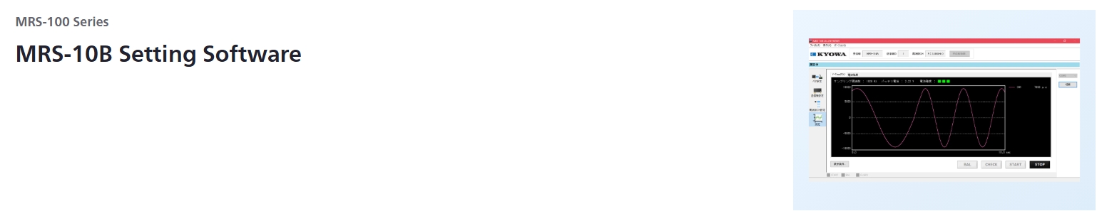
MRS-114A
|
Software Functions
Setting Functions |
Set the measuring range.
|
|---|---|
Operation Functions |
Execute balance adjustment.
|
Inspection Function |
Radio condition inspection. |
Simple Data Memo Function*
Outline |
Function for checking operation before test |
|---|---|
Save Format |
CSV |
Save Interval |
MRS-101A-S: All data, 0.01, 0.1, 1 s
|
Save Time |
Save interval all data:
|
Operating Environment
OS |
Windows® 10
|
|---|---|
CPU |
Core i5, 2 GHz or advanced |
Memory |
4 GB or more |
Interface |
USB2.0 (Can also be operated in a USB3.0 port) |
Display |
1024 × 768 or more |
*Simple recording function for operation check |